machine tool cooling pump

A technology for cooling pumps and machine tools, used in pumps, pump components, mechanical equipment, etc., can solve the problems of high-pressure fluid idling vortex loss, low lift and efficiency, and achieve improved utilization, improved efficiency, broad market prospects and promotion value. Effect

Inactive Publication Date: 2015-07-29
JIANGSU UNIV
View PDF5 Cites 0 Cited by
  • Summary
  • Abstract
  • Description
  • Claims
  • Application Information

AI Technical Summary

Problems solved by technology

[0006] In the machine tool cooling pumps in the prior art, the impeller is mainly a semi-open centrifugal impeller, that is, the inlet side of the impeller is open, the pump body is usually designed with a circular or spiral flow cross section, and there is a large axial gap between the impeller blades and the pump body. The cavity, which causes the high-pressure fluid to idle in the cavity when the pump is running, has a large vortex loss, so the lift and efficiency of this type of pump are low

Method used


Image

  • machine tool cooling pump
  • machine tool cooling pump
  • machine tool cooling pump

Examples


Embodiment 1

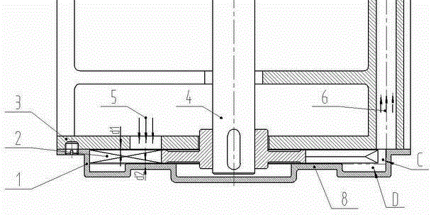
[0030] Such as figure 1 As shown in the schematic diagram of the pump head part of the machine tool cooling pump of the present invention, the present invention is mainly composed of a pump cover 1, an impeller 2, a pump body 3, and a pump shaft 4, which are arranged coaxially from bottom to top; the pump cover 1 and the pump body 3 pass through The set screws are fixed; the impeller 2 is located between the pump cover 1 and the pump body 3, and there are axial gaps d1=0.1mm and d2=0.1mm between the pump cover 1 and the pump body 3 respectively; the impeller 2 and the pump The shaft 4 is fixed and rotates in the circumferential direction relative to the pump cover 1 and the pump body 3; the pump cover 1 is provided with a radial flow passage C at the position corresponding to the width b of the impeller, and is provided with an annular protrusion 8 and a concave flow passage D; The pump body 3 is provided with a water inlet 5 and a water outlet hole 6, both of which communicat...

Embodiment 2

[0050] The machine tool cooling pump in this embodiment is also coaxially arranged sequentially from the bottom to the top by the pump cover 1, the impeller 2, the pump body 3 and the pump shaft 4; the pump cover 1 and the pump body 3 are affixed; the impeller 2 is located between the pump cover 1 and Between the pump body 3 and between the pump cover 1 and the pump body 3, there are axial clearances of d1=0.3mm and d2=0.3mm respectively; The body 3 rotates in the circumferential direction; the pump cover 1 is provided with a radial flow channel C corresponding to the impeller width b, and is provided with an annular protrusion 8 and a concave flow channel D; the pump body 3 is provided with a water inlet 5 and The water outlet hole 6 communicates with the flow channels C and D; the pump shaft 4 runs through the impeller 2 and the pump body 3 , leaving an axial gap with the pump cover 1 .

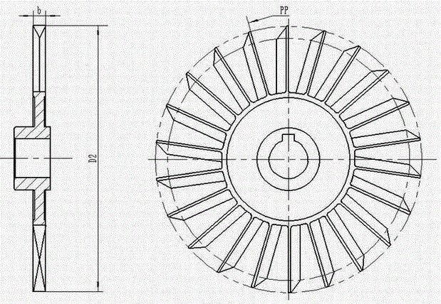
[0051] figure 2 It is a schematic diagram of the structure of the impeller 2 of the p...

Embodiment 3

[0070] The machine tool cooling pump in this embodiment consists of pump cover 1, impeller 2, pump body 3 and pump shaft 4 arranged coaxially from bottom to top; pump cover 1 and pump body 3 are fixed; impeller 2 is located between pump cover 1 and pump There are axial gaps d1=0.2mm and d2=0.2mm between the pump body 3 and between the pump cover 1 and the pump body 3 respectively; Rotate in the circumferential direction; the pump cover 1 is provided with a radial flow channel C at the position corresponding to the impeller width b, and is provided with an annular protrusion 8 and a concave flow channel D; the pump body 3 is provided with a water inlet 5 and a water outlet hole 6. It communicates with the flow channels C and D; the pump shaft 4 runs through the impeller 2 and the pump body 3, leaving an axial gap with the pump cover 1.

[0071] figure 2 It is a schematic diagram of the structure of the impeller 2 of the present invention. Considering the application of machin...


PUM


Abstract

The invention discloses a cooling pump of a machine tool. An impeller is in a full-open vortex long-blade structure; the blade length is 1 / 6-1 / 4 of the outer diameter D2 of the impeller; an axial clearance d1 between the impeller and a pump body is 0.1-0.3mm; annular bulges are arranged on a pump cover and used for adjusting an axial clearance d2 between the pump cover and the impeller to be 0.1-0.3mm; a water inlet is formed in the pump body, and takes a cut-water position A as a starting point circumferentially; and a radial position of the water inlet corresponds to a blade area of the impeller. According to the cooling pump of the machine tool, the novel vortex impeller is strictly matched with the pump cover and the end face of the pump body, and the matched clearances between the impeller and the pump cover and between the impeller and the pump cover are ensured, so that a small-flow and high-lift cooling liquid conveying requirement is met; the efficiency is improved; a distance from the water inlet to the bottom of a cooling liquid box can be shortened with the increasing of a lift; a use ratio of cooling liquid is increased; the characteristic requirements on the efficiency, small flow and high lift are met; and the cooling pump can be widely applied to cooling of the machine tool.

Description

technical field [0001] The invention belongs to the field of cooling pumps, and in particular relates to a machine tool cooling pump technology with high-efficiency and high-lift delivery. Background technique [0002] Machine tool cooling pumps are mostly installed above the predetermined coolant tank, mainly composed of pump cover 1, pump body 3, and pump shaft 4. The impeller 2 is installed in the pump cover 1, coaxial with the pump cover and pump body, and the motor drives the impeller to rotate. Deliver coolant to cool machined parts. Its pump head part, such as figure 1 As shown, it is mainly composed of pump cover 1, impeller 2, pump body 3 and pump shaft 4, which are immersed in the coolant. The maximum radial size is limited by the size of the round hole above the box to ensure that iron filings etc. Impurities do not enter the box. [0003] As the spindle speed of the machine tool increases significantly, the head of the cooling pump of the machine tool is requi...

Claims


Application Information

Patent Timeline
Patent Type & Authority Patents(China)
IPC IPC(8): F04D29/42F04D29/22
Inventor 张金凤袁寿其方玉建袁野张云蕾
Owner JIANGSU UNIV
Why Eureka
Try Eureka