An elastic locking device

A locking device and elastic technology, applied in the direction of fluid pressure actuation device, brake type, mechanical equipment, etc., can solve the problems of increased clamping force, poor rigidity, low bearing capacity, etc., to achieve increased clamping force, The effect of improving the bearing capacity and enhancing the rigidity of the machine

Inactive Publication Date: 2015-08-12
JILIN UNIV
View PDF4 Cites 0 Cited by
  • Summary
  • Abstract
  • Description
  • Claims
  • Application Information

AI Technical Summary

Problems solved by technology

[0003] The purpose of the present invention is to propose an elastic locking device, the purpose is to solve the problems of low overall load capacity and poor rigidity of the machine in the prior art, realize the continuous movement and locking function of the moving beam, increase the clamping force, For machines with extra heavy loads

Method used


Image

  • An elastic locking device
  • An elastic locking device
  • An elastic locking device

Examples


Embodiment 1

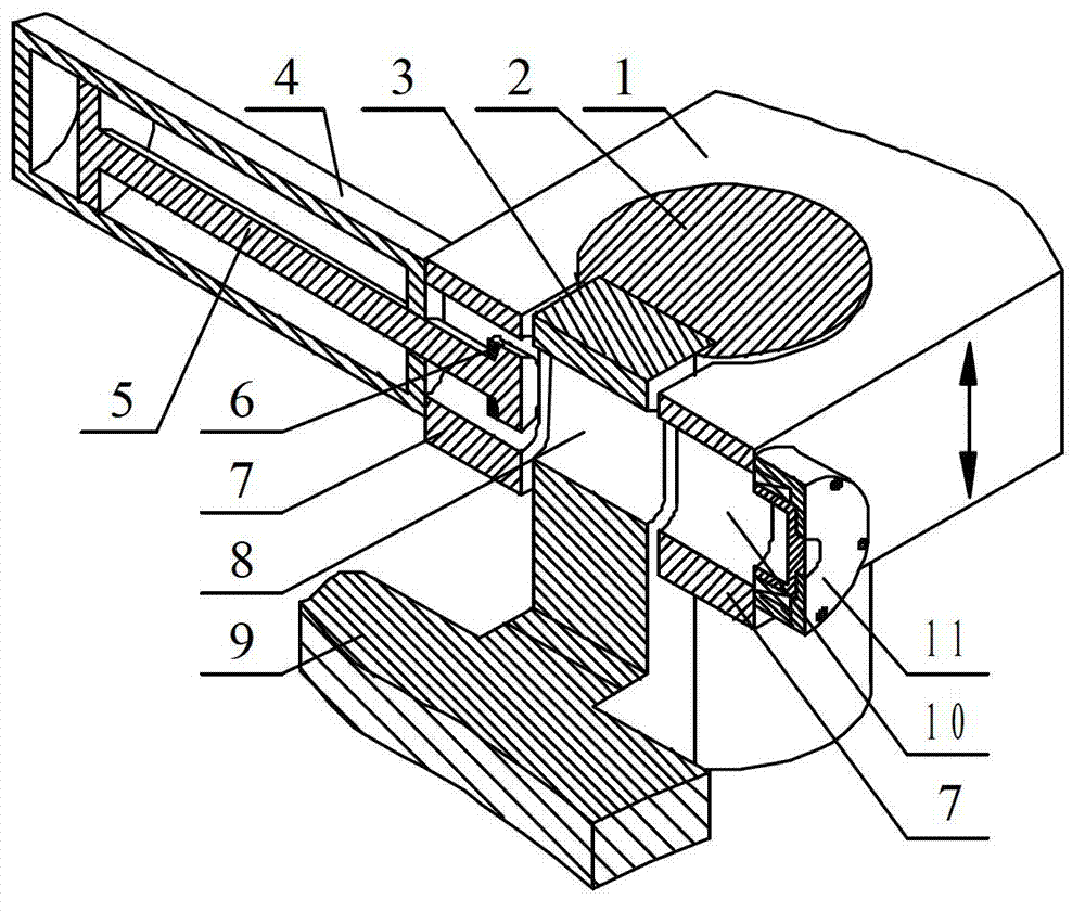
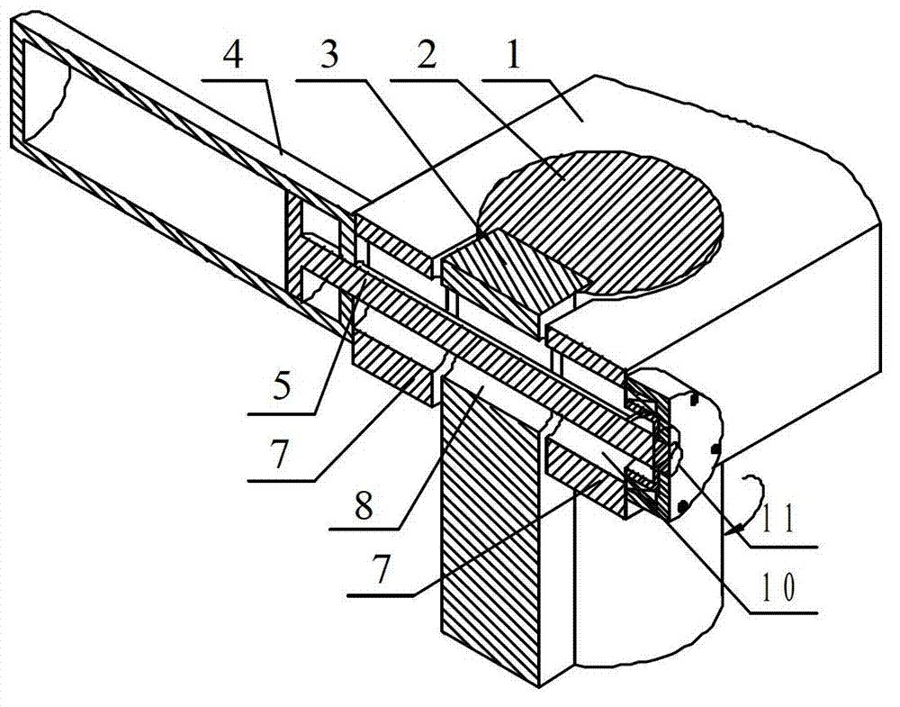
[0031] An elastic locking device of the present invention includes a non-full cylinder 2, an elastic clamp flap 7 on the moving beam 1 and a hydraulic cylinder clamping mechanism 4, and the non-full cylinder 2 is fixed to the side column 9 through a rectangular section member 3. Connected together, the movable crossbeam 1 is provided with an open round hole, and the open round hole is in clearance fit with the non-integral cylinder 2, and the two ends of the opening of the round hole are used as two elastic clips 7 of the movable crossbeam 1 The opening formed by the two elastic clips 7 leaves a certain gap margin with the rectangular section member 3, so that when the distance between the two elastic clips 7 is reduced to realize the clamping process of the non-integral cylinder 2, the two There is always a gap between the elastic clamp flaps 7 and the rectangular cross-section member 3 without contact; the distance between the two elastic clamp flaps 7 is adjusted by the hydr...

Embodiment 2

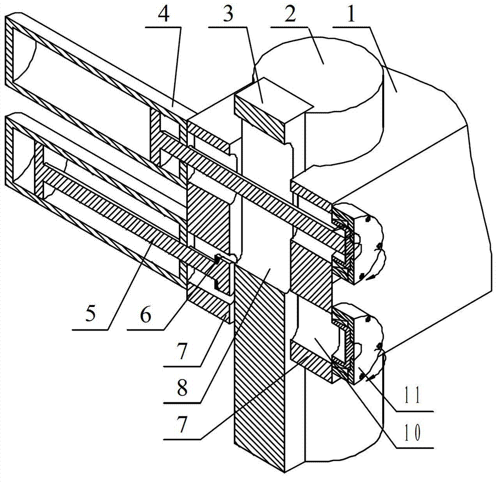
[0040] See attached Figure 4 , attached Figure 5 And attached Figure 6The difference between this implementation and Embodiment 1 is that two hydraulic cylinder clamping mechanisms 4 form a group, and the outer sides of the two elastic clamping flaps 7 are symmetrically provided with the hydraulic cylinder clamping mechanism 4, and the hydraulic cylinder The end of the piston rod 5 in the clamping mechanism 4 is a flattened disc, and the two sides of the rectangular section member 3 are symmetrically opened with T-shaped grooves in the vertical direction. 5. The flattened discs at the ends are matched with the T-shaped grooves on both sides to realize relative sliding. The hydraulic oil cylinders on both sides of the clamping mechanism 4 are filled with hydraulic oil in the rod cavity at the same time. The symmetrical hydraulic cylinder clamps on both sides The piston rod 5 in the clamping mechanism 4 moves away from the elastic clamping valve 7 at the same time to realiz...


PUM


Abstract

The invention discloses an elastic locking device, belongs to the field of fixing and clamping techniques, and aims at solving the problems of poor overall bearing capacity and poor rigidity of a machine in the prior art and achieving continuous moving and a locking function of a moving cross beam. The elastic locking device is characterized in that a non-integral cylinder is fixedly connected with a side stand column through a rectangular-section member, the non-integral cylinder is in clearance fit with an open circular hole in the moving cross beam, two ends of an opening of the circular hole are used as two elastic clamping pieces of the moving cross beam, and a clearance allowance is reserved between an opening formed by the two elastic clamping pieces and the rectangular-section member. The distance of the two elastic clamping pieces is adjusted through hydraulic oil cylinder clamping mechanisms, then the non-integral cylinder can be clamped or loosened, and at least one set of hydraulic oil cylinder clamping mechanisms can achieve clamping when the moving cross beam moves to any position. According to the elastic locking device, the side stand column can be connected with a clamping part through the arranged non-integral cylinder, the side stand column can be designed to be in any size and any structural shape, the overall bearing capacity of the machine is improved, and the rigidity of the machine is enhanced.

Description

technical field [0001] The invention belongs to the technical field of fixing and clamping, and in particular relates to an elastic locking device for a moving beam and a side column in a machine with a frame structure. Background technique [0002] In many frame-structured machines, it is required that the movable crossbeam can move continuously, and it should be locked with the side column at any position, so that they can be integrated so as to improve the rigidity of the machine. The traditional testing machine has a small working load, and the bearing requirements can be met only by the cylindrical side column. Therefore, most of them use the method of moving the beam through the cylindrical side column to implement clamping. For machines with super-heavy loads, only using cylindrical side columns to carry the load can no longer meet the requirements of the overall load-bearing capacity of the machine or cause poor rigidity; in the clamping process of traditional testin...

Claims


Application Information

Patent Timeline
Patent Type & Authority Patents(China)
IPC IPC(8): F15B15/26F16D71/00
Inventor 张学成薛广新
Owner JILIN UNIV
Why Eureka
Try Eureka