Check patentability & draft patents in minutes with Patsnap Eureka AI!

Projected capacitive touch panel

A touch panel, projected capacitance technology, applied in the direction of electrical digital data processing, instrumentation, data processing input/output process, etc., can solve the problem of inability to sense capacitance changes, reduce the effect of touch sensing, and control the circuit to calculate the touch position And other issues

Active Publication Date: 2013-08-21
SILICON INTEGRATED SYSTEMS
View PDF9 Cites 2 Cited by
  • Summary
  • Abstract
  • Description
  • Claims
  • Application Information

AI Technical Summary

Problems solved by technology

However, maintaining this coverage leaves a large gap between adjacent electrodes, reducing the effect of touch sensing
If the user's fingers are relatively slender or the user uses a stylus, the electrodes close to the touch point may not be able to sense the change in capacitance, and the control circuit cannot calculate the correct touch position through interpolation, resulting in a tactile sensation. Incorrect
As the design of the stylus becomes thinner and thinner, the touch panel is bound to be more and more affected by this shortcoming in order to meet the requirements

Method used


Image

  • Projected capacitive touch panel
  • Projected capacitive touch panel
  • Projected capacitive touch panel

Examples


Embodiment Construction

[0025] In order to make the above objects, features and advantages of the present invention more comprehensible, preferred embodiments of the present invention are exemplified below and described in detail in conjunction with the accompanying drawings. Furthermore, the directional terms mentioned in the present invention, such as "up", "down", "front", "back", "left", "right", "inside", "outside", "side", etc., It is only for orientation with reference to the attached drawings. Therefore, the directional terms used are used to illustrate and understand the present invention, but not to limit the present invention.

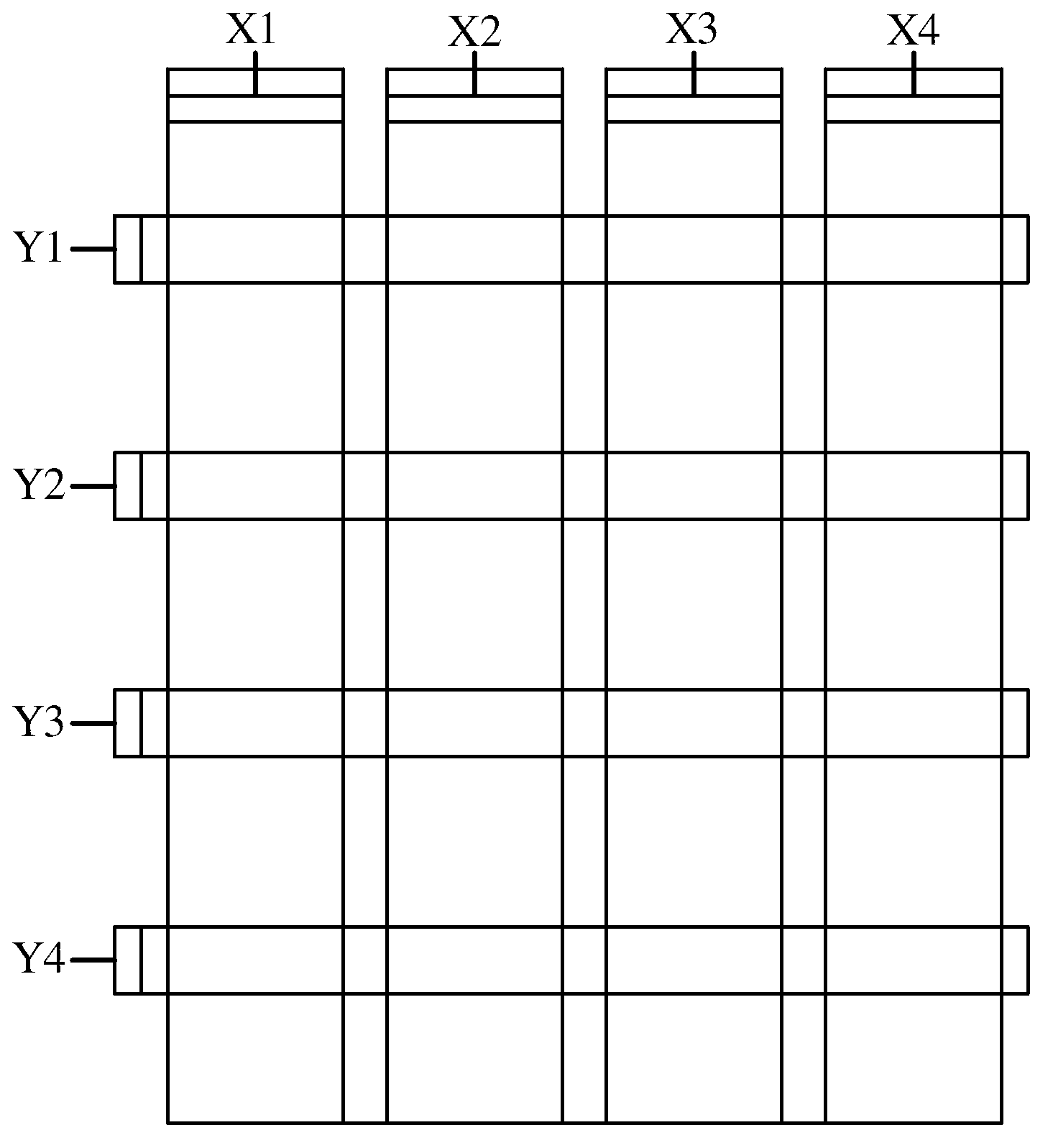
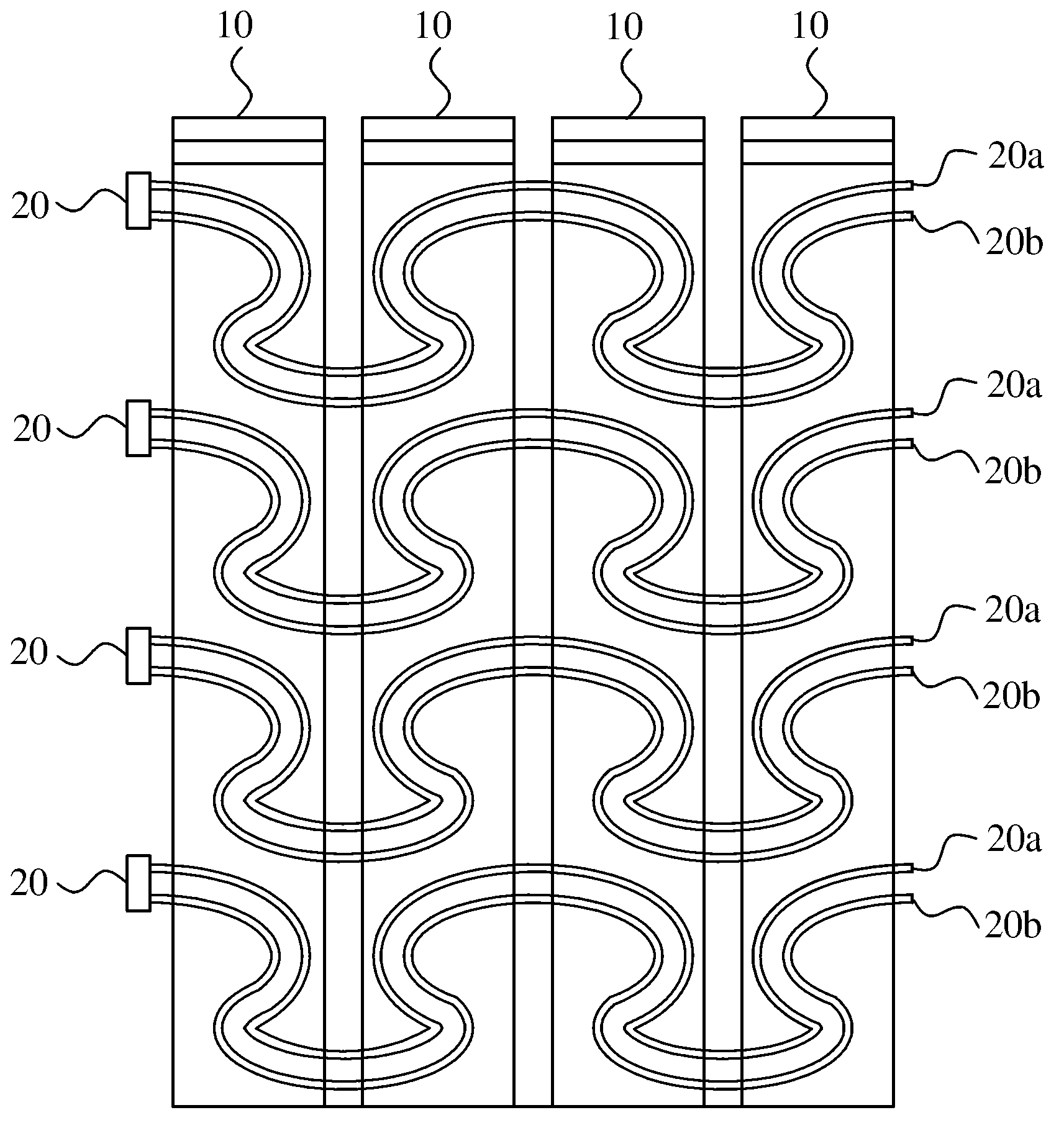
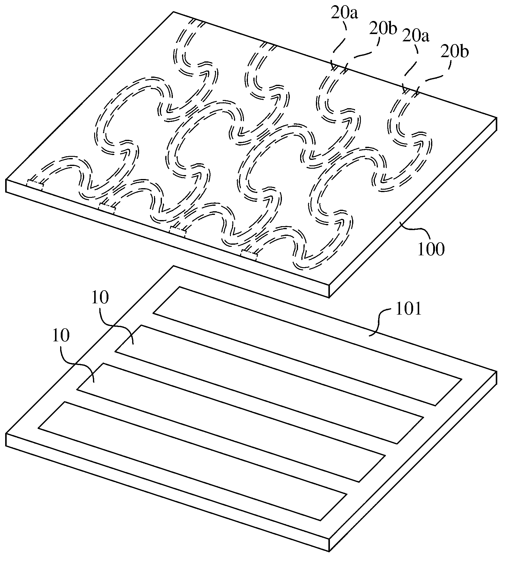
[0026] Please refer to figure 2 As shown, the projected capacitive touch panel of the present invention includes a plurality of first electrodes 10 and a plurality of second electrodes 20 intersecting with the first electrodes 10 . The arrangement of the first electrode 10 and the second electrode 20 is used to define a sensing area, and is used to respectively ...


PUM


Abstract

A projected capacitive touch panel has a plurality of bar shaped first electrodes arranged parallel to each other and a plurality of wiggly-shaped second electrodes separated from each other by a space and each including a plurality of sensing lines. The sensing lines of each second electrode are spaced from each other by an interval, electrically connected to each other and extend along an oriented direction perpendicular to the length direction of the first electrodes in a wiggly manner. The sensing lines that are separated from each other by a short interval improve touch sensing effect.

Description

technical field [0001] The invention relates to a touch panel, in particular to a projected capacitive touch panel capable of increasing touch accuracy. Background technique [0002] A projected capacitive touch panel generally includes two sets of transparent electrodes (X and Y) and a plurality of driving lines connected to the transparent electrodes, wherein the two sets of transparent electrodes are respectively arranged on two different substrates or are arranged together on a single substrate. [0003] Please refer to figure 1 As shown, a conventional projected capacitive touch panel includes a set of X electrodes (X1-X4) and another set of Y electrodes (Y1-Y4) perpendicular to the set of X electrodes. The X and Y electrodes are connected to a control circuit through a plurality of driving lines, thereby forming a sensor array. The control circuit can sense the capacitance change between the X electrode and the Y electrode to determine the position touched by a user...

Claims


Application Information

Patent Timeline
Patent Type & Authority Applications(China)
IPC IPC(8): G06F3/044
CPCG06F2203/04112G06F3/0446
Inventor 徐日明
Owner SILICON INTEGRATED SYSTEMS
Features
  • R&D
  • Intellectual Property
  • Life Sciences
  • Materials
  • Tech Scout
  • Unparalleled Data Quality
  • Higher Quality Content
  • 60% Fewer Hallucinations
Learn More