Waste wire stripping device

A wire stripping device and wire technology, applied in the direction of dismantling/armouring cable equipment, etc., can solve the problems of losing the wire tube bundle to be stripped, damaging the wire core, and complex structure, etc., and achieve the effect of ensuring the peeling effect

Active Publication Date: 2013-08-21
CHANGSHU HONGLIN WIRE & CABLE CO LTD
View PDF15 Cites 32 Cited by
  • Summary
  • Abstract
  • Description
  • Claims
  • Application Information

AI Technical Summary

Problems solved by technology

These patent and special issue application schemes generally have the disadvantages of complex structure, troublesome use and high investment cost
[0004] The "a new type of cable stripping system" recommended by the authorized announcement number CN202633843U has the advantages of a concise structure compared to the aforementioned patents. The blade knife (patent called stripping tool) can only remove the cortex (that is, the aforementioned outer sheath) on one side of the length direction of the wire to be stripped, while the rest of the cortex is still wrapped around the wire core, so the take-up reel closes It is impossible to collect the completely exposed wire core during the line, so the patented solution cannot be put into use in essence, unless the outer sheath is grabbed by a special person before the line is taken up by the take-up reel
[0005] In addition to the foregoing problems, CN20623384U also has the following deficiencies: one, because the wire to be stripped is for the peeling knife to peel off the outer sheath extruding from the

Method used


Image

  • Waste wire stripping device
  • Waste wire stripping device
  • Waste wire stripping device

Examples


Embodiment Construction

[0024] In order to enable examiners of the Patent Office, especially the public, to more clearly understand the technical essence and beneficial effects of the present invention, the applicant will describe in detail in the form of examples below, but the description of the examples is not intended to describe the solution of the present invention. As a limitation, any equivalent transformations made according to the concept of the present invention that are merely formal rather than substantive should be regarded as the technical solution scope of the present invention.

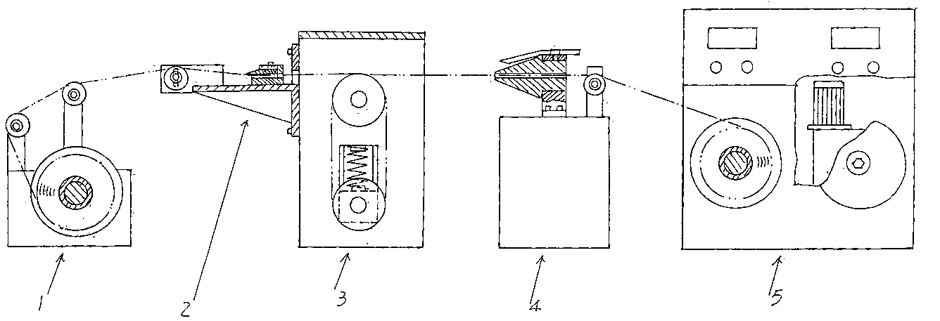
[0025] See figure 1 , As currently figure 1 The position shown as an example shows the pay-off mechanism 1, the peeling mechanism 2, the automatic tension adjustment mechanism 3, the peeling mechanism 4, and the core winding mechanism 5 set from left to right, that is, the peeling mechanism 2 is located between the pay-off mechanism 1 and the automatic tension adjustment mechanism 3, and the peeling mechanism 4 ...


PUM


Abstract

The invention discloses a waste wire stripping device, and belongs the technical field of recovery devices of waste materials. The waste wire stripping device comprises a paying-off mechanism, a paring mechanism, a tension automatic adjustment mechanism, a peeling mechanism and a wire core winding mechanism, wherein the paring mechanism is arranged on one side of the tension automatic adjustment mechanism, the peeling mechanism is located between the tension automatic adjustment mechanism and the wire core winding mechanism, the paring mechanism comprises a fixed plate, a paring knife fixing base supporting arm, a paring knife fixing base, a paring knife and a guiding wheel, the fixed plate is fixed with one side of the tension automatic adjustment mechanism, a wire passing hole is formed in the fixed plate, the paring knife fixing base supporting arm is fixed with one side of the fixed plate, a wire passing groove is formed in one side of the paring knife fixing base, two ends of the paring knife are respectively provided with a paring knife adjustment groove, the guiding wheel is arranged on a guiding wheel shaft, the guiding wheel shaft is fixed on a guiding wheel shaft base, and the guiding wheel shaft base is fixed on the paring knife fixing base supporting arm. The waste wire stripping device is ideal in stripping effect, free of damage to the guiding wheel caused by friction, long in service life and low in knife cost, and ensures a paring effect.

Description

Technical field [0001] The invention belongs to the technical field of waste material recovery devices, and specifically relates to a waste wire stripping device, which is used to separate the outer sheath and the core of the scrapped wire, so as to recover the core and outer sheath materials to save resources. Background technique [0002] It is well known that in the cable production process, serious defects and scrapped cables are usually inevitable, and the internal core of the cable (usually copper core, aluminum core, aluminum-clad copper or copper-clad aluminum core) can be recycled Utilization, and the outer sheath outside the core (usually called the insulating sheath) can also be recycled. Therefore, the stripping device is an indispensable special recycling device for waste materials that wire and cable manufacturers are willing to accept. Otherwise, relying on manual recycling, that is, manual removal of the outer protective layer, will at least produce the following...

Claims


Application Information

Patent Timeline
IPC IPC(8): H02G1/12
Inventor 赖恒俊
Owner CHANGSHU HONGLIN WIRE & CABLE CO LTD
Why Eureka
Try Eureka