Light-emitting diode (LED) driver and lighting device with same

A technology for LED drivers and lighting devices, applied in lighting devices, output power conversion devices, instruments, etc., can solve the problem of high cost

Inactive Publication Date: 2013-08-21
OSRAM GMBH
View PDF0 Cites 2 Cited by
  • Summary
  • Abstract
  • Description
  • Claims
  • Application Information

AI Technical Summary

Problems solved by technology

This secondary LED driver connects a boost input unit and an additional filter capacitor C1 after the rectifier bridge. The boost input unit is directly connected to the filter capacitor C1 to maintain the voltage in the filter capacitor C1, but this Requires an additional control IC and control switch
Although this scheme reduces the ripple current in the main output well, its cost is high

Method used


Image

  • Light-emitting diode (LED) driver and lighting device with same
  • Light-emitting diode (LED) driver and lighting device with same
  • Light-emitting diode (LED) driver and lighting device with same

Examples


Embodiment Construction

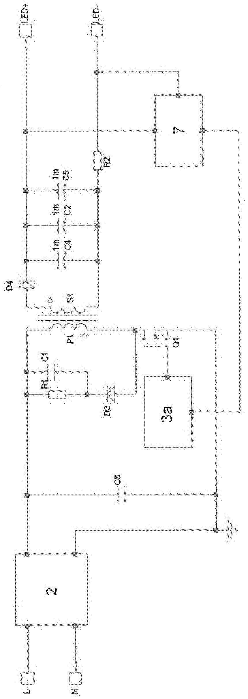
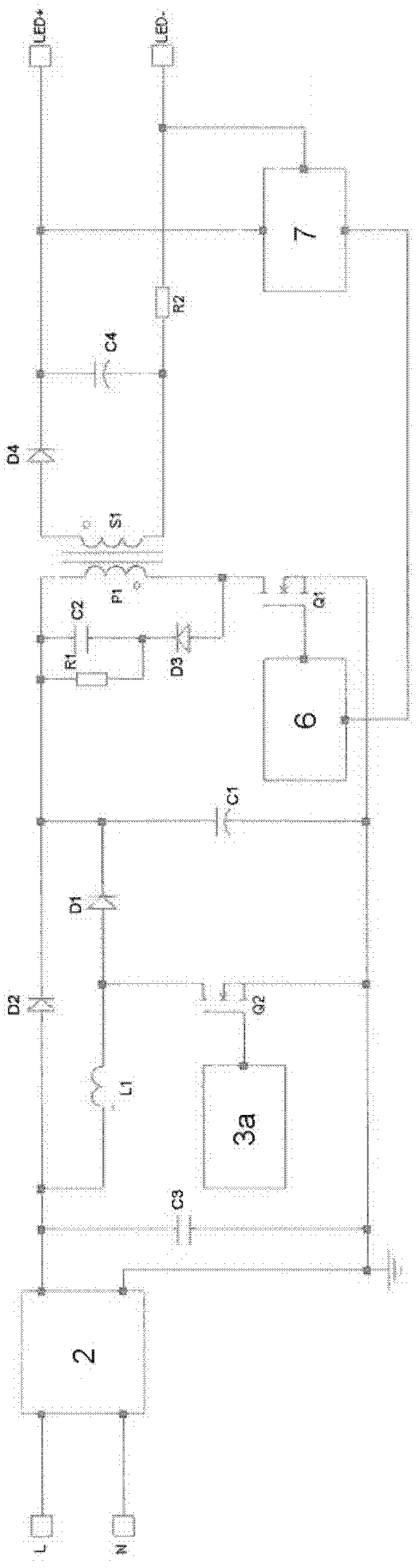
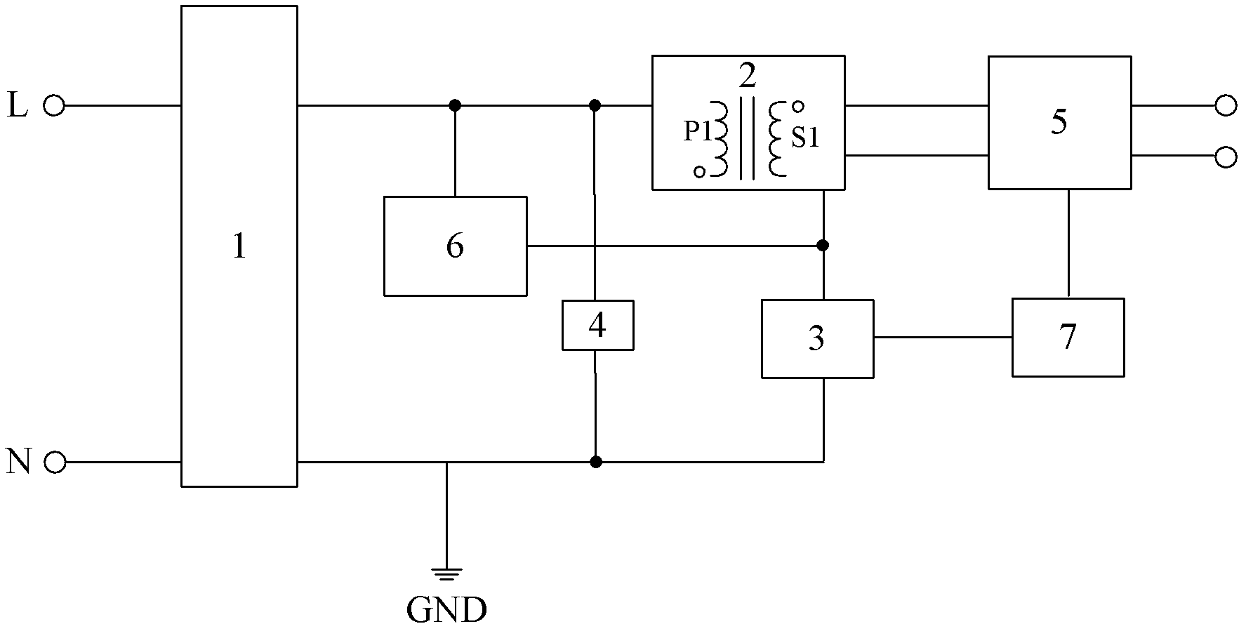
[0027] image 3 A functional block diagram of an LED driver according to the present invention is shown. As can be seen from the figure, the LED driver includes a rectifier bridge 1; a converter 2 connected to the rectifier bridge 1, the converter 2 includes a primary coil P1 and a secondary coil S1; a primary filter unit 4, the first end of the primary filter unit 4 Connected between the first end of the primary coil P1 and the rectifier bridge 1, the second end is connected to the ground GND; the switch unit 3, connected to the second end of the primary coil P1, controls the connection between the primary coil P1 and the ground GND; and the secondary The stage output unit 5 is connected to the secondary coil S1. It can be further seen from the figure that the LED driver also includes a boost input unit 6, the first end of the boost input unit 6 is connected between the rectifier bridge 1 and the first end of the primary coil P1, and the second end of the boost input unit 6 ...


PUM


Abstract

The invention relates to a light-emitting diode (LED) driver which comprises a rectifier bridge (1), a converter (2), a primary filtering unit (4), a switch unit (3) and a secondary output unit (5). The converter (2) is connected to the rectifier bridge (1) and comprises a primary coil (P1) and a secondary coil (S1), the first end of the primary filtering unit (4) is connected between the first end of the primary coil and the rectifier bridge(1), the second end of the primary filtering unit (4) is connected to the ground (GND), the switch unit (3) is connected to the second end of the primary coil (P1), the switch unit (3) controls the primary coil (P1) to be connected with the ground, and the secondary output unit (5) is connected to the secondary coil. The LED driver further comprises a boost input unit (6), wherein the first end of the boost input unit (6) is connected between the rectifier bridge and the first end of the primary coil, and the second end of the boost input unit is connected to the second end of the primary coil. When the switch unit is connected, the boost input unit and the primary coil are charged, and the primary filtering unit is discharged through the primary coil. When the switch unit is disconnected, the boost input unit is discharged through the primary coil, and charging current is provided for the primary filtering unit. The invention further relates to a lighting device with the LED driver.

Description

technical field [0001] The invention relates to an LED driver for a lighting device. In addition, the present invention also relates to an illuminating device having the above-mentioned type of LED driver. Background technique [0002] As a cold light source, LED lighting device has the advantages of pure light color, concentrated beam, high color rendering index, good temperature characteristics, low power consumption, stable performance, long life, no pollution, and easy to use. In order to drive the LED light source, a large number of different types of AC-DC LED drivers have appeared on the market, including single-stage LED drivers and two-stage LED drivers. But they each have different advantages and disadvantages. For example, a single-stage LED driver is simple in structure, low in cost, and can provide good power factor, but it has relatively large ripple current. Otherwise, some problems may arise in some applications. For example, in indoor applications, large...

Claims


Application Information

Patent Timeline
IPC IPC(8): H05B37/02H02M3/155H05B44/00
CPCH05B45/382H05B45/38Y02B20/30H05B45/385
Inventor 魏泽科米凯莱·梅尼加兹庄锡河林丹
Owner OSRAM GMBH
Why Eureka
Try Eureka