Steering column device

A technology of steering column and steering shaft, applied in steering column, steering control, steering mechanism, etc.

Inactive Publication Date: 2013-08-21
NSK LTD
View PDF12 Cites 4 Cited by
  • Summary
  • Abstract
  • Description
  • Claims
  • Application Information

AI Technical Summary

Problems solved by technology

However, Japanese Patent Application Laid-Open No. 2010-52639 does not describe that when the adjustment rod 22 is strongly pressed against the front edge of the vertical long hole 21a during a secondary collision, it is used to alleviate the impact on the driver's body. Technology

Method used


Image

  • Steering column device
  • Steering column device
  • Steering column device

Examples


Embodiment Construction

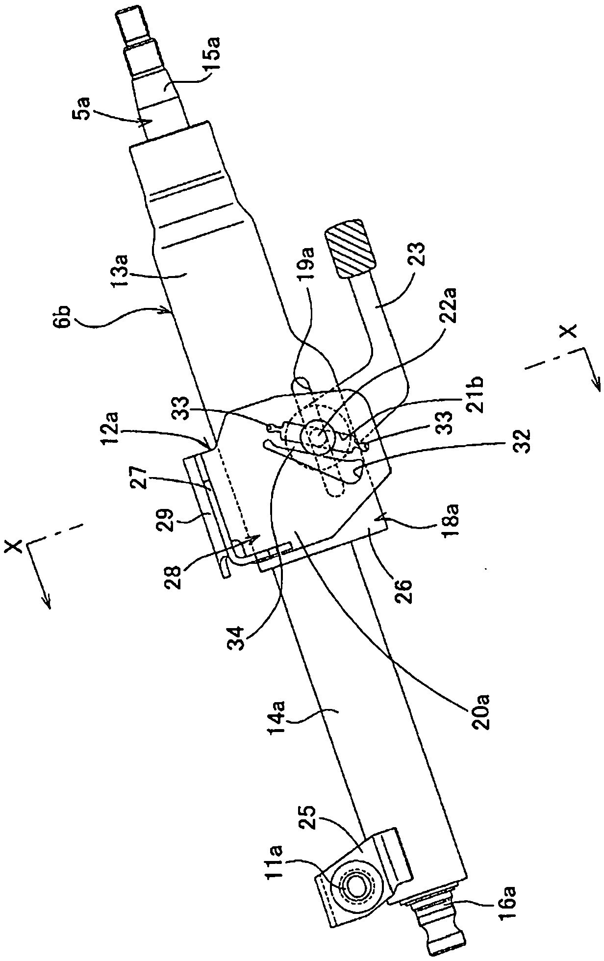
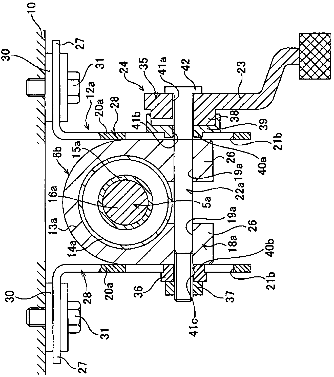
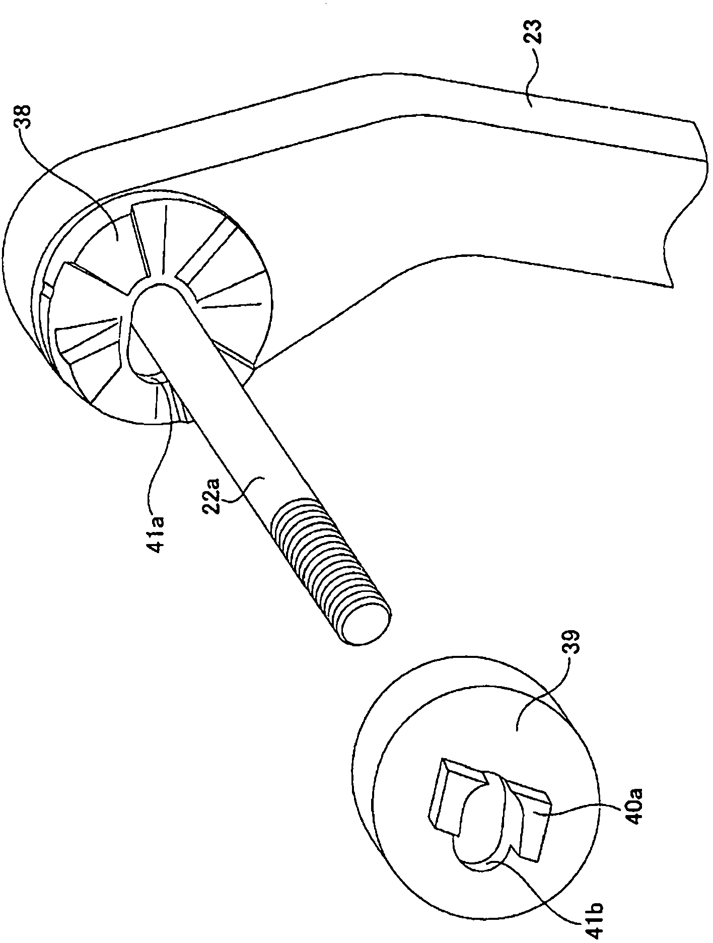
[0046] Figure 1 to Figure 6 One example of the embodiment of the present invention is shown. In this example, a telescopic mechanism is provided in addition to the tilt mechanism, and the steering column device of the present invention is applied to a tilt / telescopic steering device. The steering column device of this example has a steering column 6b, a displacement bracket 18a, a longitudinal long hole (through hole) 19a, a support bracket 12a, a vertical long hole 21b, a through hole 32, and a zoom device 24. Furthermore, in the configuration in which the telescopic mechanism is omitted, instead of providing the front-rear direction long hole 19a, the through hole is constituted by a simple circular hole.

[0047] In the case of the present example, the steering column 6b has an axial relative displacement so that the front end portion of the outer column 13a arranged on the rear side and the rear end portion of the inner column 14a arranged on the front side are fitted so...


PUM


Abstract

In a tilt-type steering apparatus, a steering column device structure is realized whereby the impulse imparted to the body of a driver can be mitigated even when an adjusting lever (22a) is vigorously pushed against the front edge of a vertically elongated hole (21b) during a secondary collision. A through-hole (32) continuing from the top end part of the vertically elongated hole (21b) to the bottom end part thereof is formed in a portion of a pair or left and right support plates (20a) of a support bracket (12a), in a portion thereof forward of the vertically elongated hole (21b). A bridge part (34) is provided between the forward edge of the vertically elongated hole (21b) and the rearward edge of the through-hole (32). The bridge (34) mitigates an impulse by elastically deforming in the forward direction on the basis of the impulse load imparted in the forward direction from a steering column (6b) via the adjusting lever (22a) during a collision event.

Description

technical field [0001] The present invention relates to a steering column device for rotatably supporting a steering shaft supporting a steering wheel on a vehicle body in a tilt steering device capable of adjusting the vertical position of a steering wheel. Background technique [0002] like Figure 7 As shown, the steering device for an automobile is configured to transmit the rotation of the steering wheel 1 to the input shaft 3 of the steering gear unit 2, and with the rotation of the input shaft 3, a pair of left and right tie rods 4 are pushed and pulled to give a steering angle to the front wheels. The steering wheel 1 is supported and fixed to a rear end portion of a steering shaft 5 , and the steering shaft 5 is rotatably supported by the steering column 6 in a state where the steering shaft 5 is inserted through the cylindrical steering column 6 in the axial direction. In addition, a front end portion of the steering shaft 5 is connected to a rear end portion of an...

Claims


Application Information

Patent Timeline
Patent Type & Authority Applications(China)
IPC IPC(8): B62D1/19B60R21/05
CPCB62D1/184B62D1/195B62D1/187
Inventor 森山诚一
Owner NSK LTD
Why Eureka
Try Eureka