
Electrical power resistor

A technology of power resistors and resistors, applied in the direction of resistors, resistor sets, resistor components, etc.

Active Publication Date: 2013-08-21
VISHAY ELECTRONICS
View PDF3 Cites 2 Cited by
  • Summary
  • Abstract
  • Description
  • Claims
  • Application Information

AI Technical Summary

Problems solved by technology

However, due to the intermediate spaces created between these adjoining transverse webs, the respective resistor plates are bendable

Method used


Image

  • Electrical power resistor
  • Electrical power resistor
  • Electrical power resistor

Examples


Embodiment Construction

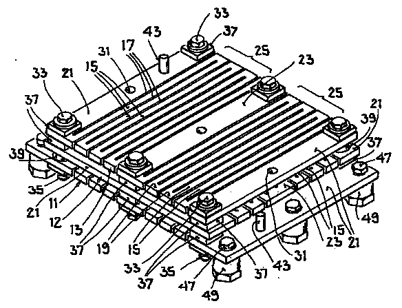
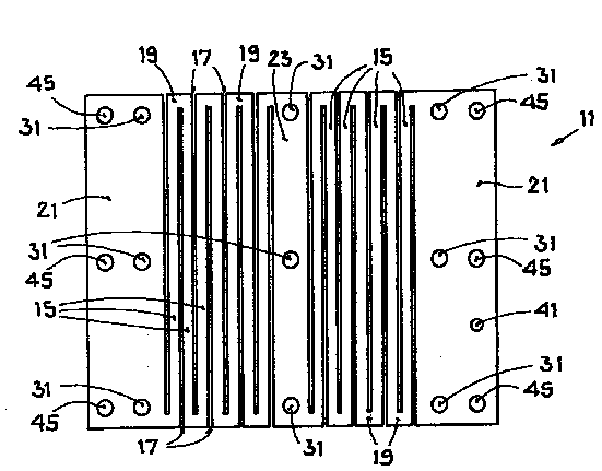
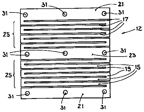
[0028] exist figure 1 , the power resistor comprises a stack of resistor plates arranged in a plane-parallel manner with respect to each other, i.e. there is a first resistor plate 11 ( figure 2 ), the second resistor plate 12 ( image 3 ) and the third resistor plate 13 ( Figure 4 ). The rectangular resistor plates 11 , 12 , 13 comprise metal, typically stainless steel or other suitable alloys, and may also have rounded corners other than those presented in FIGS. 1 to 4 . The resistor plates 11 , 12 , 13 are fastened to each other and electrically conductively connected to each other, as will be explained below.

[0029] Each resistor plate 11 , 12 , 13 has a meander structure formed with a plurality of transverse webs 15 next to each other. Mutually adjoining transverse webs 15 are spaced apart from each other by strip-shaped intermediate spaces 17 and are connected to each other with short connecting webs 19 . For example in Figure 4 As shown in the third resistor ...


PUM


Abstract

The invention relates to an electrical power resistor, comprising a stack of a plurality of resistor plates made of metal. Each resistor plate has at least one serpentine structure which is formed by a plurality of crosspieces alternately connected to one another. Successive resistor plates in the stacking direction are rotated by 90 DEG relative to one another.

Description

technical field [0001] This invention relates to an electrical power resistor, typically used in generators and frequency converters. Such power resistors are suitable for converting electrical energy into thermal energy in power plants during special operating conditions in which the electrical energy typically exhibits a significant reduction during a period of milliseconds to seconds. This is the case, for example, for wind turbines and water power plants. Background technique [0002] Such a power resistor may be formed from a stack of metal resistor plates, each resistor plate of the stack having at least one meandering structure connected to each other by a plurality of transverse webs. Formed by following and being spaced apart from each other. This provides a resistor unit which can be easily adapted to the respective application with a simple construction. [0003] However, mechanical stability problems may occur with such resistor units. That is, if a current f...

Claims


Application Information

Patent Timeline
IPC IPC(8): H01C1/016H01C7/00
CPCH01C1/016H01C7/001H01C7/00H01C1/00
Inventor 伯特伦·肖特奥托·汉普尔
Owner VISHAY ELECTRONICS
Learn More