Combined cylinder valve

A gas cylinder valve, combined technology, applied in the field of gas cylinder valves, can solve troubles and other problems

Active Publication Date: 2013-08-28
NINGBO XINGJIAN SPACE MACHINERY
View PDF6 Cites 8 Cited by
  • Summary
  • Abstract
  • Description
  • Claims
  • Application Information

AI Technical Summary

Problems solved by technology

[0002] The commonly used gas cylinder valve usually has only one switch function. The gas cylinder valve and the pressure reducing valve are installed separately. When inflating, remove the pressure reducing valve and inflate the gas cylinder through the gas cylinder valve. A pressure reducing valve is installed on the bottle valve to output the decompressed gas to the outside. From the above process, it can be seen that when inflating and delivering gas to the outside, people have to dismantle and install the pressure reducing valve cyclically, which is more troublesome to operate.

Method used


Image

  • Combined cylinder valve
  • Combined cylinder valve
  • Combined cylinder valve

Examples


Embodiment Construction

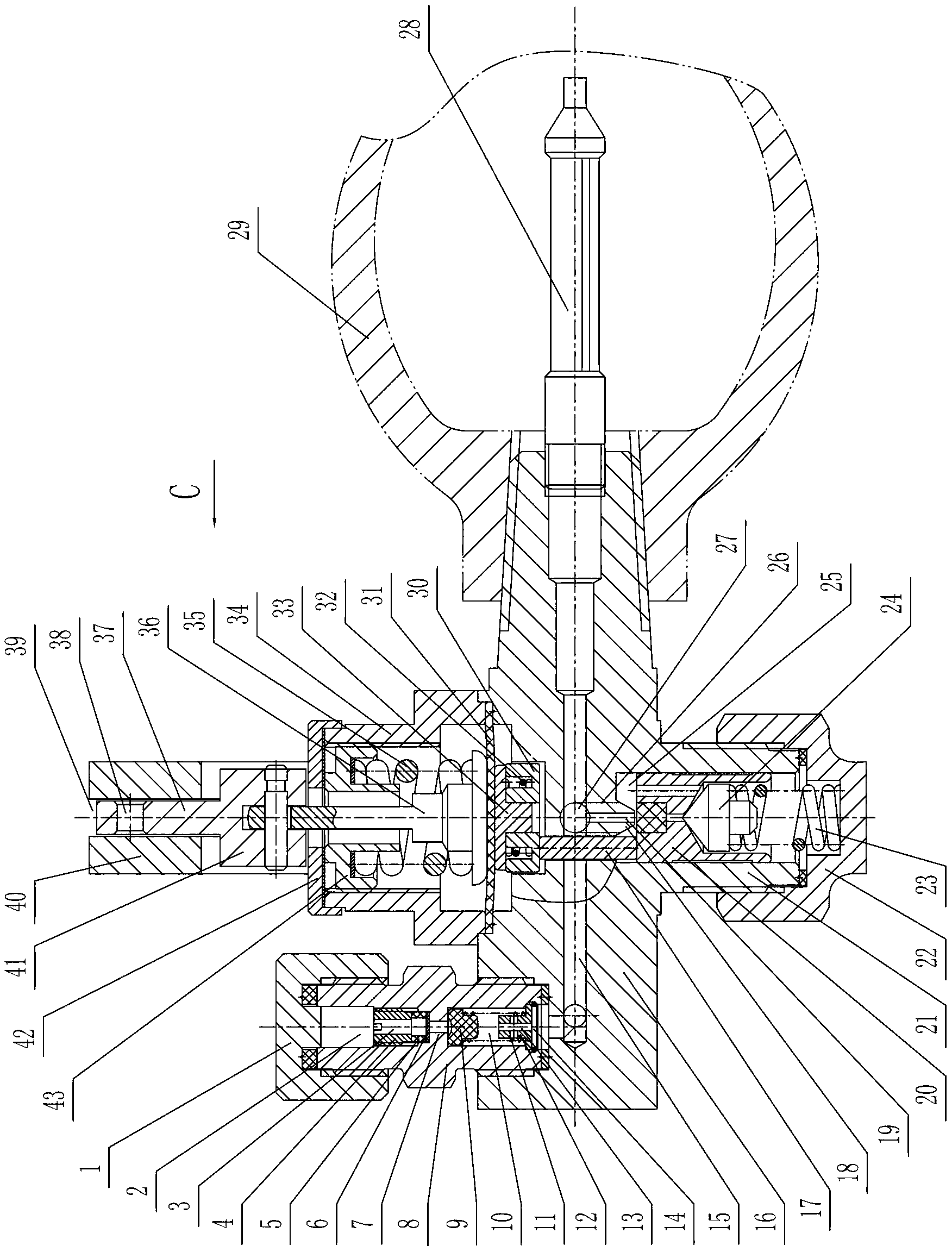
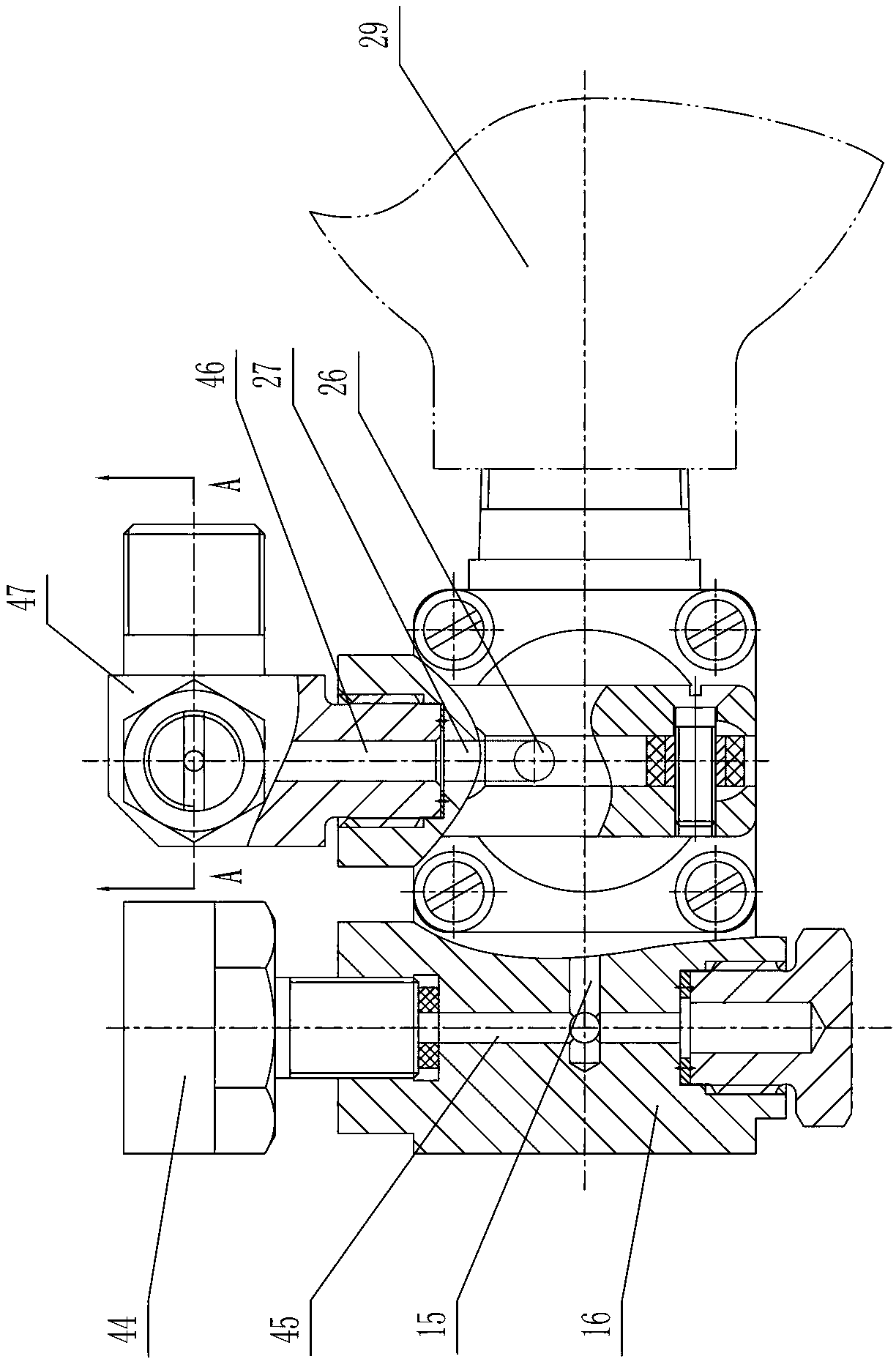
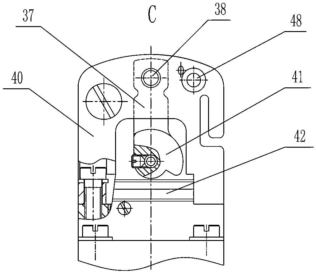
[0020] The combined gas cylinder valve of the present invention will be further described below in conjunction with the accompanying drawings and specific embodiments:

[0021] Such as figure 1 , figure 2 , image 3 with Figure 4As shown, in this specific embodiment, the combined gas cylinder valve of the present invention includes a main valve body 16, the right end of the main valve body 16 is used to be threadedly connected with the gas cylinder 29, and the main valve body 16 is provided with a main channel 15 and an air outlet channel 27. The right end of the main channel 15 is connected with a filter 28, the right end of the main channel 15 communicates with the gas cylinder 29 through the filter 28, and the main valve body 16 at the left end of the main channel 15 is connected with a one-way valve. The first valve body 8 connected to the body 16, the first valve body 8 is provided with an air inlet chamber 2 and an air outlet chamber 10 communicating with the inlet ...


PUM


Abstract

The invention provides a combined cylinder valve, and belongs to a cylinder valve. The combined cylinder valve comprises a main valve body. The right end of the main valve body is used for being in threaded connection with an air cylinder. A main channel and an air outlet channel are arranged on the main valve body. A filter is connected at the right end of the main channel. The right end of the main channel is communicated with the air cylinder through the filter. A check valve is connected on the main valve body at the left end of the main channel. A pressure reducing valve with a switch function is arranged on the main valve body between the main channel and the air outlet channel. A pipe joint is connected on the exit of the air outlet channel. A joint channel on the pipe joint is communicated with the air outlet channel. A safety valve is arranged on the pipe joint. A pressure gauge is connected on the main valve body and communicated with the main channel through a side channel. The combined cylinder valve has the advantages that switching of air inflation or outward air delivery can be realized only by pulling a handle, inserting a dowel or pulling up the dowel by people, so that troubles in demounting and mounting of the pressure reducing valve are avoided, and great convenience is brought to people to operate.

Description

Technical field: [0001] The invention relates to a gas cylinder valve, in particular to a combined gas cylinder valve integrated with the functions of a one-way valve, a pressure reducing valve and a safety valve. Background technique: [0002] The commonly used gas cylinder valve usually has only one switch function. The gas cylinder valve and the pressure reducing valve are installed separately. When inflating, remove the pressure reducing valve and inflate the gas cylinder through the gas cylinder valve. The bottle valve is equipped with a pressure reducing valve to output the decompressed gas to the outside. From the above process, it can be seen that when inflating and conveying gas to the outside, people have to dismantle and install the pressure reducing valve cyclically, which is troublesome to operate. Invention content: [0003] The technical problem to be solved by the present invention is to provide a combined gas cylinder valve that does not need to disassembl...

Claims


Application Information

Patent Timeline
Patent Type & Authority Applications(China)
IPC IPC(8): F16K15/18F16K31/524
Inventor 汪秀勇
Owner NINGBO XINGJIAN SPACE MACHINERY
Why Eureka
Try Eureka