Workstation system for solar water heater

A technology for solar water heaters and workstations, applied in solar thermal power generation, solar thermal devices, heating devices, etc., can solve the problems of wasting electricity, gradually decreasing, and unable to take a bath for users, achieving low installation costs and waste of electricity. Effect

Inactive Publication Date: 2013-08-28
李芳
View PDF7 Cites 7 Cited by
  • Summary
  • Abstract
  • Description
  • Claims
  • Application Information

AI Technical Summary

Problems solved by technology

At present, when solar water heaters in ordinary households store water, the water is transported to the water storage tank located at a high place through a water pump. When in use, the heated water flows to the bathroom where the water outlet is located by virtue of its own water pressure. However, the amount of water storage that determines the water pressure gradually decreases with the use of hot water, resulting in insufficient flow of hot water from the faucet to allow users to take a bath happily. In order to solve this problem, existing users install solar water heaters Generally, a water pump is installed on the water outlet pipe. With the help of the external force of the water pump, the little water in the water storage tank is pulled out with the greatest force, so as to achieve the same effect when the water pressure is high. However, the added water pump is also increased cost
[0003] The biggest factor affecting the use effect of solar water heaters is the intensity of light and the time of light. When the collector is not exposed to enough light, the temperature of the water often does not meet the comfort level required by people. Therefore, it is generally installed in the water storage tank. The heater raises the temperature of the water to a set temperature, but it is obviously a waste of electricity to have an electric heater keep heating the entire tank of water for this purpose

Method used


Image

  • Workstation system for solar water heater

Examples


Embodiment Construction

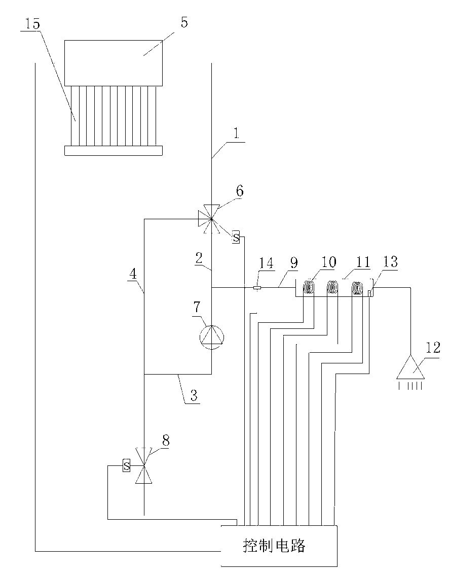
[0011] The details of its implementation and its working principle are specifically described below in conjunction with the accompanying drawings:

[0012] like figure 1 As shown, the solar water heater workstation system includes a first water pipe 1 connected to the solar water heater tank 5 and a water pump 7, a three-way valve 6 is provided between the water pump 7 and the solar water heater water tank 5, and the first interface of the three-way valve 6 The first water pipe 1 is connected to the water tank 5, the second port of the three-way valve 6 is connected to one end of the water pump 7 through the second water pipe 2, and the other end of the water pump 7 is connected to the water supply valve 8 through the third water pipe 3. A fourth water pipe 4 is connected between the three water pipe 3 and the third interface of the three-way valve 6, and a hot water outlet pipe 9 is also connected to the second water pipe 2, and the water in the hot water outlet pipe 9 passes...


PUM


Abstract

The invention relates to a workstation system for a solar water heater. The workstation system is powerful in water outlet, low in mounting cost and energy saving. The system comprises a first water tube and a water pump which are communicated with a water tank of the solar water heater. The system is characterized in that a three-way valve is arranged between the water pump and the first water tube, a first connecting port of the three-way valve is connected with the first water tube, a second connecting port of the three-way valve is connected with one end of the water pump through a second water tube, the other end of the water pump is connected with a water supply valve through a third water tube, a fourth water tube is connected between the third water tube and a third connecting port of the three-way valve, and a hot water outlet tube is further communicated with the second water tube. According to the workstation system for the solar water heater, heated water can flow faster, wasted electric energy of electrical heating is little, and the mounting cost is low.

Description

technical field [0001] The invention relates to a solar water heater, in particular to a solar water heater workstation system. Background technique [0002] As one of the most energy-efficient and clean new energy sources, solar energy is increasingly widely used in people's lives. Especially the use of solar water heaters: Looking down from a high place, you can see solar collectors reflecting sunlight on the roof or balcony of buildings everywhere. At present, when the solar water heaters in ordinary households store water, the water is transported to the high water storage tank through the water pump. When in use, the heated water flows to the bathroom where the faucet is located by its own water pressure. However, the water storage capacity that determines the water pressure gradually decreases with the use of hot water, resulting in insufficient hot water flow rate from the faucet to allow users to take a bath happily. In order to solve this problem, existing users in...

Claims


Application Information

Patent Timeline
Patent Type & Authority Applications(China)
IPC IPC(8): F24J2/00F24J2/46
CPCY02E10/40
Inventor 李芳
Owner 李芳
Why Eureka
Try Eureka