
Liquid crystal display and optical compensation method thereof

A liquid crystal display and optical compensation technology, applied in optics, optical components, nonlinear optics, etc., can solve the problems of poor contrast ratio and small viewing angle range at large viewing angles, and achieve the effect of reducing light leakage in dark states

Active Publication Date: 2013-08-28
TCL CHINA STAR OPTOELECTRONICS TECH CO LTD
View PDF5 Cites 12 Cited by
  • Summary
  • Abstract
  • Description
  • Claims
  • Application Information

AI Technical Summary

Problems solved by technology

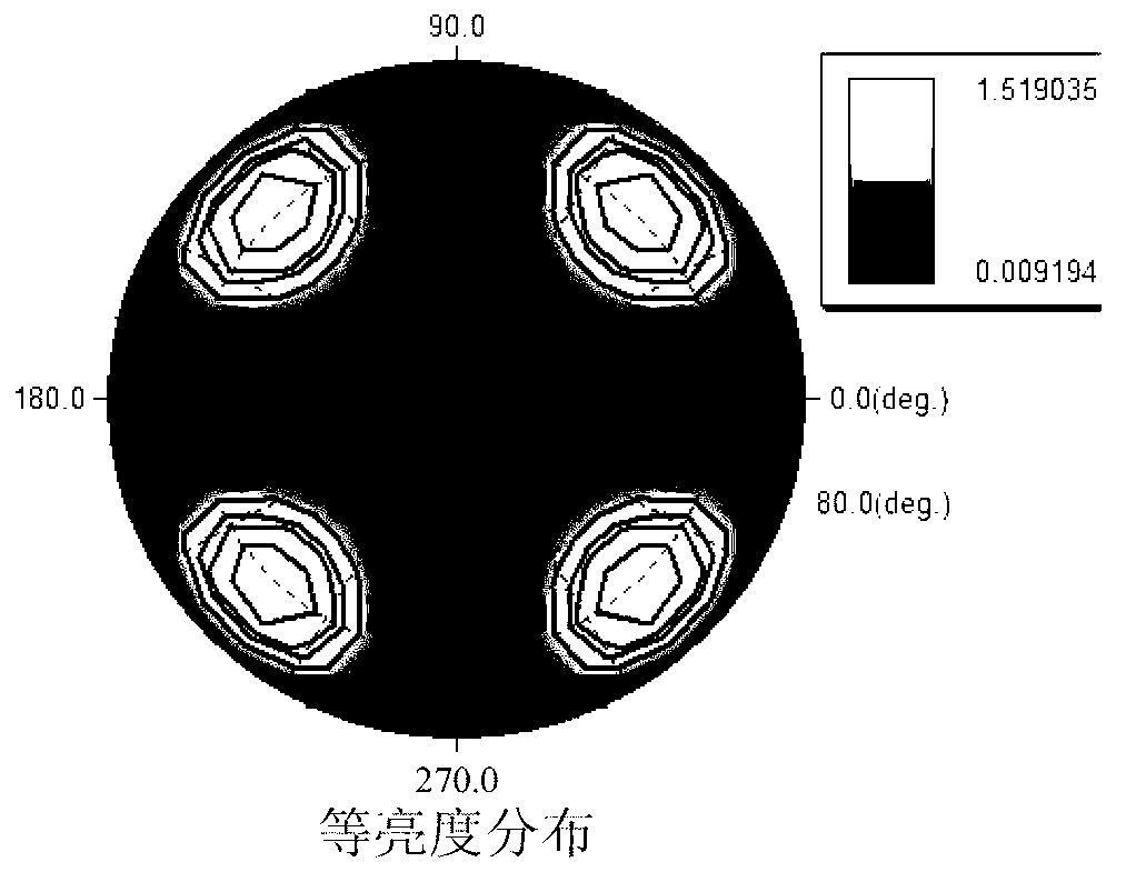
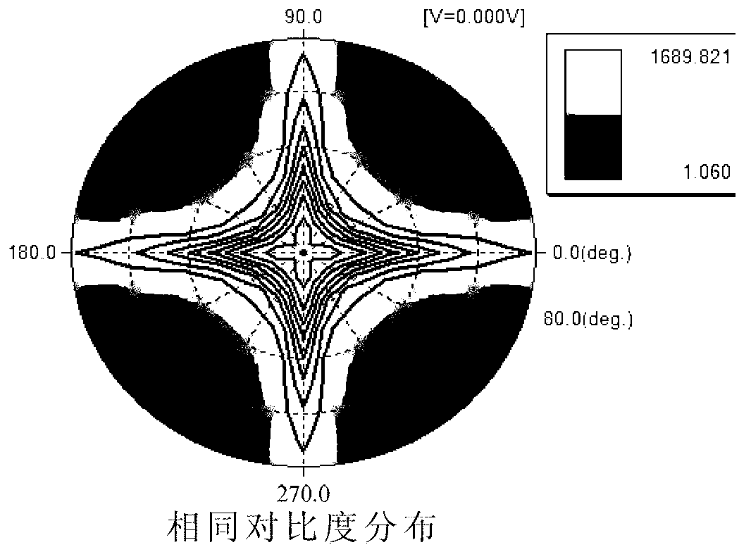
[0007] from figure 1 and figure 2 It is not difficult to see that with the A-Plate and C-Plate compensation values ​​of the prior art, there will be serious light leakage when viewing large viewing angles in a dark state, the contrast of large viewing angles will become poor, and the viewing angle range is small

Method used


Image

  • Liquid crystal display and optical compensation method thereof
  • Liquid crystal display and optical compensation method thereof
  • Liquid crystal display and optical compensation method thereof

Examples


Embodiment Construction

[0045] The following descriptions of the various embodiments refer to the accompanying drawings to illustrate specific embodiments in which the present invention can be practiced. The directional terms mentioned in the present invention, such as "up", "down", "front", "back", "left", "right", "inside", "outside", "side", etc., are for reference only The orientation of the attached schema. Therefore, the directional terms used are used to illustrate and understand the present invention, but not to limit the present invention. In the figures, structurally similar units are denoted by the same reference numerals.

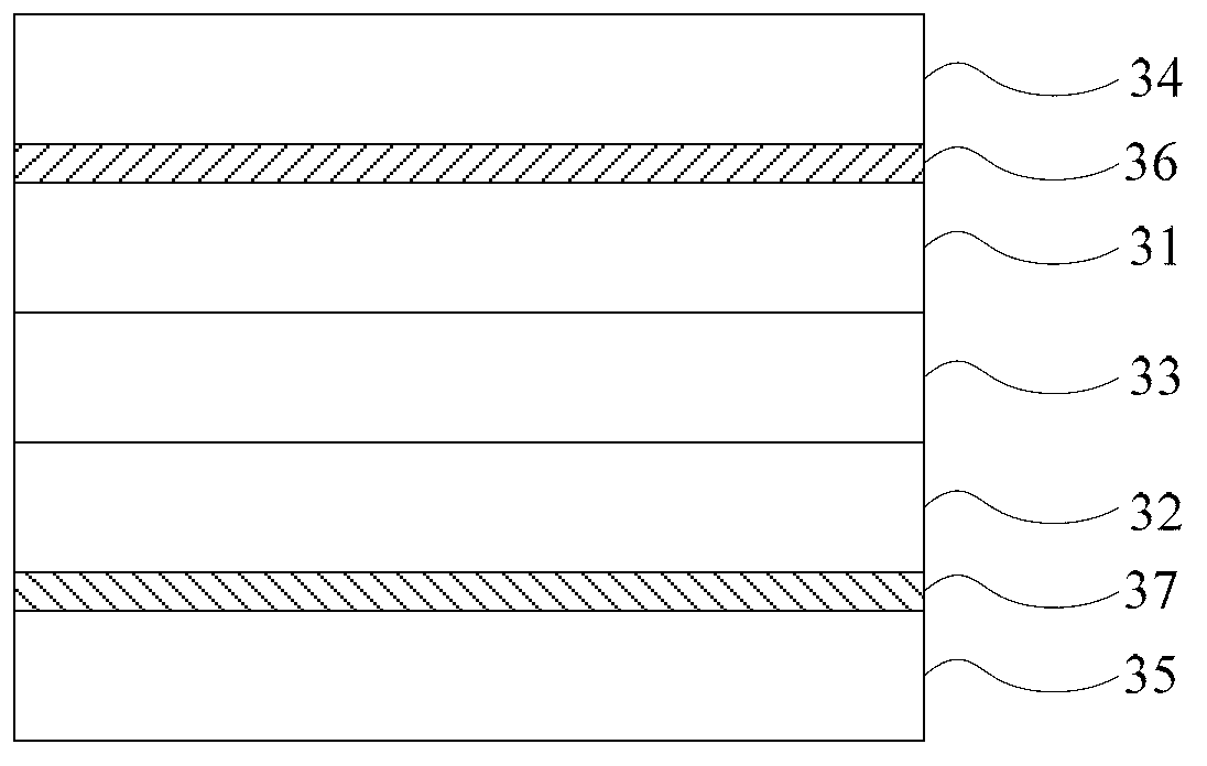
[0046] see image 3 , image 3 It is a structural schematic diagram of the first preferred embodiment of the liquid crystal display in the embodiment of the present invention.

[0047] The liquid crystal display in the embodiment of the present invention is preferably a vertical alignment (Vertical Alignment, VA) liquid crystal display, and the wavelength range of ...


PUM


Abstract

The invention discloses a liquid crystal display and an optical compensation method thereof. The liquid crystal display and the optical compensation method thereof aim at compensating a liquid crystal display with a uniaxial positive birefringence A-plate and a uniaxial negative birefringence C-Plate, specifically aim at changing compensation values of the uniaxial positive birefringence A-plate and the uniaxial negative birefringence C-Plate, and particularly aim at controlling a value range of the compensation value Rth of the uniaxial negative birefringence C-Plate. By weakening dark state light leakage phenomenon by adjusting the compensation values of the two plates, an embodiment of the liquid crystal display and the optical compensation method thereof can effectively weaken the dark state light leakage phenomenon at large viewing angles, and contrast ratio and definition of the large viewing angles are increased.

Description

【Technical field】 [0001] The invention relates to the technical field of liquid crystal display, in particular to a liquid crystal display and an optical compensation method thereof. 【Background technique】 [0002] With the continuous popularization of liquid crystal display panels, the requirements for display quality of liquid crystal display panels are getting higher and higher. Taking Thin Film Transistor LCD (TFT-LCD) as an example, as the viewing angle of TFT-LCD gradually increases, the contrast of the picture decreases continuously, and the definition of the picture also gradually decreases. This is due to the fact that the birefringence of the liquid crystal molecules in the liquid crystal layer changes with the change of the viewing angle. Compensating with a wide viewing angle compensation film can effectively reduce the light leakage of the dark state screen and greatly improve the image quality within a certain viewing angle. contrast. [0003] The compensatio...

Claims


Application Information

Patent Timeline
Patent Type & Authority Applications(China)
IPC IPC(8): G02F1/13363
CPCG02B5/3083G02F1/13363G02F1/133634G02F2413/02G02F1/133528
Inventor 康志聪海博
Owner TCL CHINA STAR OPTOELECTRONICS TECH CO LTD
Learn More