
Optical compensator for liquid crystal display

a liquid crystal display and optical compensation technology, applied in the direction of instruments, roads, constructions, etc., can solve the problems of reducing contrast and inability to meet the performance of conventional compensation films, and achieve the effect of improving contras

Active Publication Date: 2009-12-15
INNOLUX CORP
View PDF6 Cites 3 Cited by
  • Summary
  • Abstract
  • Description
  • Claims
  • Application Information

AI Technical Summary

Benefits of technology

The present patent provides an optical compensator for a liquid crystal display that overcomes the problems of previous compensators. The optical compensator includes an A-plate and a C-plate, which act as protective films for the inner sides of the polarizer. The A-plate has in-plane retardation at wavelengths of 450 nm and 550 nm, while the C-plate has retardation at wavelengths of 650 nm and 550 nm. The A-plate and C-plate are optimized for blue light and red light, respectively. The optical compensator can be used in a liquid crystal display with a triacetate cellulose film as the protective layer. The technical effect of the present patent is to provide an improved optical compensator for a liquid crystal display that can effectively compensate for the phase retardation of the protective layer and the biaxial plate, and reduce the impact of the triacetate cellulose film on the compensation.

Problems solved by technology

However, the VA LCD still has problems of color shift or narrow viewing angle due to a dark-state light leakage at large viewing angles which reduces the contrast.
However, the performance of conventional compensation films are not acceptable since all of them are optimized for a single wavelength of light while not considering other wavelengths of the electromagnetic spectrum which are visible by human eyes.

Method used


Image

  • Optical compensator for liquid crystal display
  • Optical compensator for liquid crystal display
  • Optical compensator for liquid crystal display

Examples


Embodiment Construction

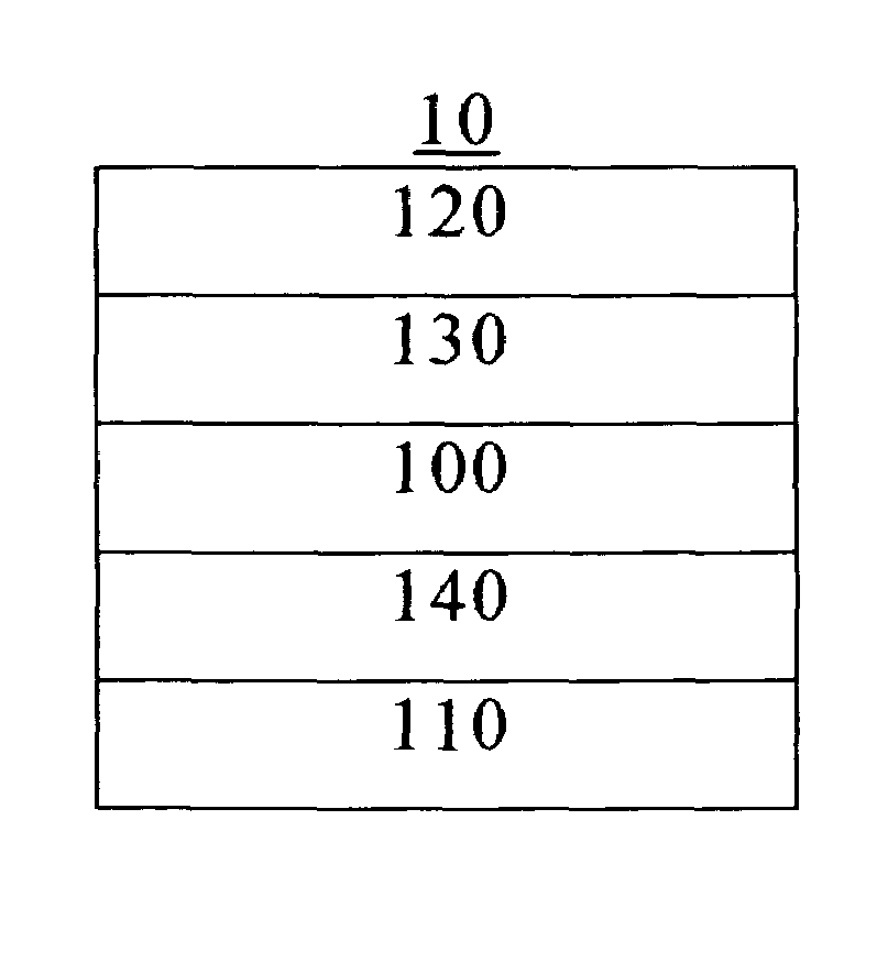
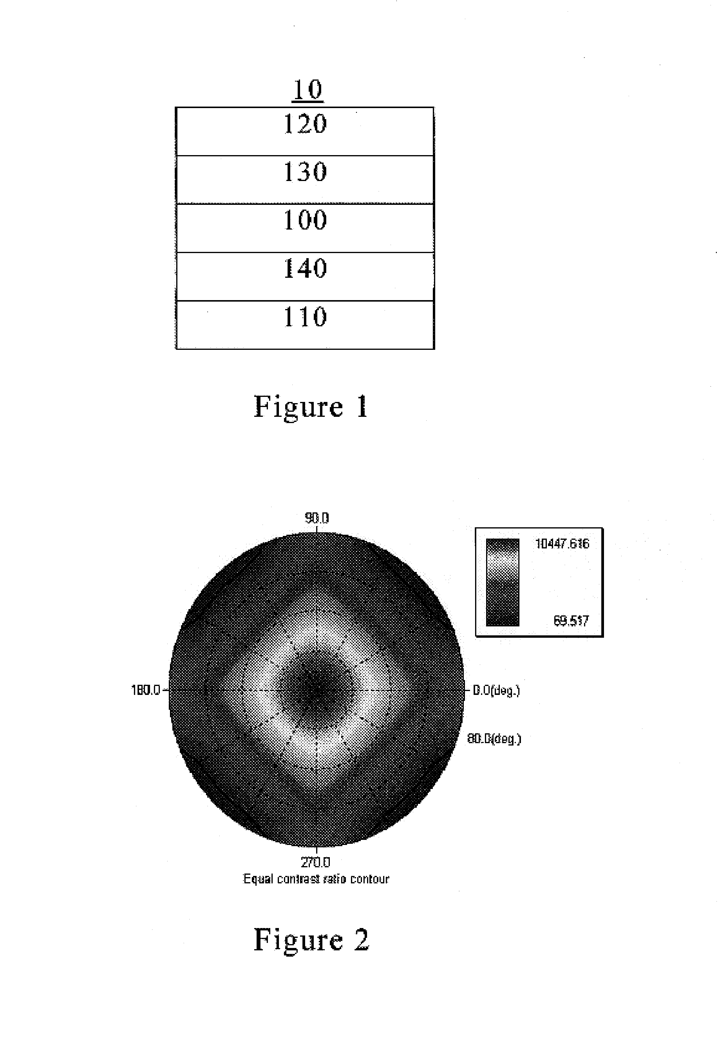
[0049]FIG. 1 shows a liquid crystal display 10 according to one embodiment of the present disclosure. The liquid crystal display 10 mainly includes a vertically-aligned (VA) LCD cell 100 positioned between two polarizers 110 and 120 which are arranged to be crossed such that their absorbing axes are orthogonal to each other.

[0050]An A-plate and a C-plate are respectively inserted between the polarizers 110 and 120 and the liquid crystal display cell 100 to reduce dark-state light leakage and increase the contrast, wherein the optic axis of the A-plate is arranged at an angle of 90 degrees to the absorbing axis of the polarizer located on the same side. In this embodiment, since the polarizer only consists of an absorbing layer, the liquid crystal display 10 is not provided with any other compensation plate except the A-plate 130 and the C-plate 140. Conventional A-plates and C-plates are typically optimized only for green light (550 nm) because human eyes are most sensitive to green...


PUM

PropertyMeasurementUnit
wavelengthsaaaaaaaaaa
wavelengthaaaaaaaaaa
wavelengthsaaaaaaaaaa

Abstract

Embodiments of an optical compensator for a liquid crystal display is disclosed. One embodiment of the optical compensator includes an A-plate and a C-plate wherein:the retardation of the A-plate satisfies the following formula:0.644<R0(450) / R0(550)<1the retardation of the C-plate satisfies the following formula:1<Rth(450) / Rth(550)<1.35where R0(450) and R0(550) represent the retardation of the A-plate at wavelengths of 450 nm and 550 nm, respectively, and Rth(450) and Rth(550) are the values calculated by Rth=[[nx+ny] / 2−nz]×d (where nx, ny and nz represent the three-dimensional refractive indexes of the C-plate as the refractive indexes in the direction of the x-axis, y-axis and z-axis, respectively, and d represents the thickness of the C-plate) for the C-plate at a wavelength of 450 nm and 550 nm, respectively. Other embodiments are also included.

Description

BACKGROUND[0001]1. Field of the Disclosure[0002]The present disclosure relates to an optical compensator for enhancing the viewing angle of a liquid crystal display.[0003]2. Description of the Related Art[0004]Recently, various liquid crystal display (LCD) modes and compensation films have been proposed to enhance the viewing angle of LCDs. Vertically-aligned (VA) LCD is a typical example of LCDs with wide viewing angle. Vertically-aligned (VA) LCD is a mode using a negative liquid crystal material and vertical alignment film. When no voltage is applied, liquid crystal molecules are aligned in a vertical direction and black display appears. When a predetermined voltage is applied, the liquid crystal molecules are aligned in a horizontal direction and white display appears. Comparing to the twisted nematic (TN) LCD, the vertically-aligned (VA) LCD provides higher contrast, higher response speed, and excellent viewing angle characteristics. However, the VA LCD still has problems of co...

Claims


Application Information

Patent Timeline
Patent Type & Authority Patents(United States)
IPC IPC(8): G02F1/1335G02F1/13363G02B5/30
CPCG02F1/13363G02F1/133634G02F2413/02G02F2001/133637G02F1/133637E01C9/08E01C11/24
Inventor LIN, TSUNG-HSIENHSIEH, MING-FENG
Owner INNOLUX CORP
Learn More