
Optical Differential Quadrature Phase Shift Keying Demodulator

A differential quadrature phase shift and demodulator technology, applied in the field of demodulators, can solve the problems of high insertion loss and polarization dependent loss, many optical devices, large insertion loss and polarization dependent loss, etc., and achieve good temperature stability , Reduce production cost, change the effect of optical path difference

Active Publication Date: 2016-05-04
HISENSE BROADBAND MULTIMEDIA TECH
View PDF7 Cites 0 Cited by
  • Summary
  • Abstract
  • Description
  • Claims
  • Application Information

AI Technical Summary

Problems solved by technology

[0005] Due to the large insertion loss and polarization-dependent loss in the performance of optical waveguide technology, and the high temperature sensitivity of the refractive index, the optical demodulator based on optical waveguide technology has high insertion loss and polarization-dependent loss, which requires more precise temperature control. And due to the high price of equipment required for optical waveguide technology and large investment, the cost of optical demodulators based on optical waveguide technology is high
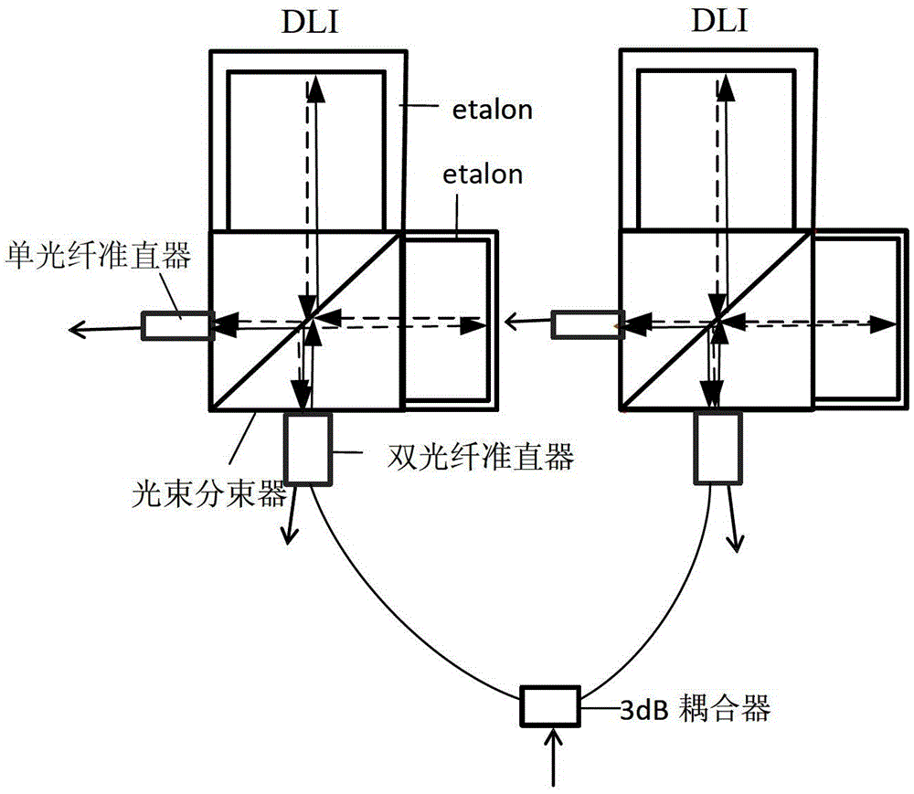
In addition, the demodulator based on Etalon technology cannot share devices between the two time-delay interferometers, resulting in the use of more optical devices, so the volume is larger, and the phase separation is achieved by changing the length of etalon, the process is complicated, and the adjustment is difficult.

Method used


Image

  • Optical Differential Quadrature Phase Shift Keying Demodulator
  • Optical Differential Quadrature Phase Shift Keying Demodulator
  • Optical Differential Quadrature Phase Shift Keying Demodulator

Examples


Embodiment Construction

[0025] The technical solutions of the various embodiments of the present invention will be clearly and completely described below in conjunction with the accompanying drawings. Apparently, the described embodiments are only some of the embodiments of the present invention, not all of them. Based on the embodiments of the present invention, all other embodiments obtained by persons of ordinary skill in the art without making creative efforts belong to the protection scope of the present invention.

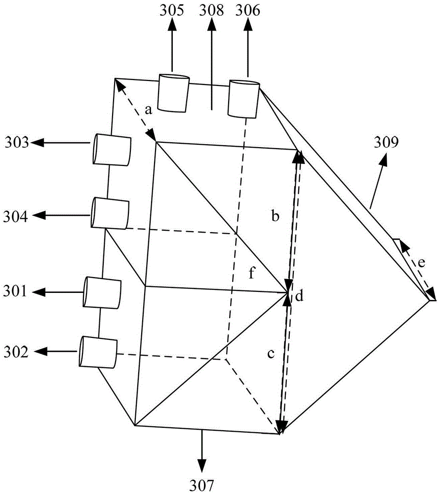
[0026] image 3 It is a schematic diagram of the three-dimensional structure of the optical differential quadrature phase shift keying format demodulator according to the first embodiment of the present invention. see image 3 , comprising: a first input light collimator 301, a second input light collimator 302, a first output light collimator 303, a second output light collimator 304, a third output light collimator 305, a fourth An output light collimator 306 , a first beam spli...


PUM


Abstract

The invention discloses an optical differential quadrature phase shift keying demodulator. The optical differential quadrature phase shift keying demodulator comprises a first input light collimator, a second input light collimator, a first light beam splitter, a second light beam splitter, a rectangular prism, a first output light collimator, a second output light collimator, a third output light collimator and a fourth output light collimator. The two input light collimators are respectively used for converting an optical signal into collimated light and outputting the collimated light to the first light beam splitter, the first light beam splitter is used for conducting transmission and reflection on the received collimated light, the rectangular prism is used for conducting two-time reflection on received light beams and outputting the received light beams to the second light beam splitter, the second light beam splitter is used for conducting transmission and reflection on the received light beams, the four output light collimators are respectively used for converging the received light beams and outputting the converged light beams. The optical differential quadrature phase shift keying demodulator is compact in structure, small in size and good in temperature stability.

Description

technical field [0001] The invention relates to a demodulator, in particular to an optical differential quadrature phase-shift keying demodulator. Background technique [0002] In high-speed optical fiber transmission systems (40G / 100G), differential quadrature phase shift keying DQPSK (Differential Quadrature Phase Shift Keying) signal modulation technology is commonly used. DQPSK is a multi-level differential phase shift keying format. The four phase differences between represent the transmitted bit information. At the receiving end based on the differential phase modulation format, a demodulator is required to convert the phase modulation into intensity modulation to extract the information in the code and differential phase. Currently, the demodulator generally It adopts optical waveguide technology and Etalon technology to design and realize. [0003] In the demodulator based on optical waveguide technology, the DQPSK demodulator is composed of two delay interferometer...

Claims


Application Information

Patent Timeline
Patent Type & Authority Patents(China)
IPC IPC(8): H04B10/556H04B10/67
Inventor 陈思乡
Owner HISENSE BROADBAND MULTIMEDIA TECH
Learn More