
Orifice plate for controlling solids flow, methods of use thereof and articles comprising the same

A technology of solid particles and orifice plates, applied in the field of orifice plates, can solve problems such as low efficiency of heat exchangers, failure of components, poor heat transfer performance, etc.

Active Publication Date: 2013-08-28
GENERAL ELECTRIC TECH GMBH
View PDF7 Cites 0 Cited by
  • Summary
  • Abstract
  • Description
  • Claims
  • Application Information

AI Technical Summary

Problems solved by technology

[0007] If hot solids and / or ash in a moving bed heat exchanger are not moved and drained evenly, large temperature differences can occur across the heat exchanger and these large temperature differences can lead to heat exchanger inefficiency or component failure
Misdistribution of solid particle flow can lead to poor heat transfer performance, resulting in inefficient use of surfaces, resulting in conditions exceeding allowable temperatures and / or stresses, and possibly causing steam temperature imbalances

Method used


Image

  • Orifice plate for controlling solids flow, methods of use thereof and articles comprising the same
  • Orifice plate for controlling solids flow, methods of use thereof and articles comprising the same
  • Orifice plate for controlling solids flow, methods of use thereof and articles comprising the same

Examples


example 1

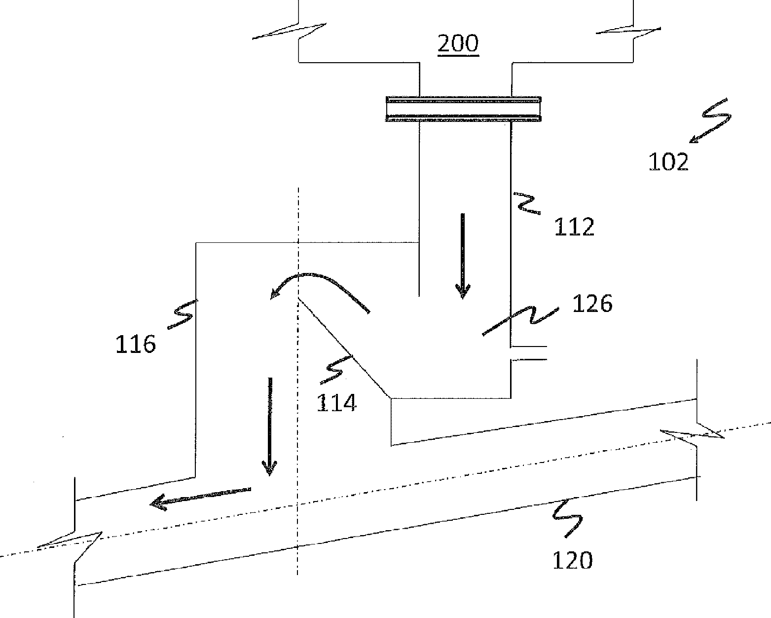
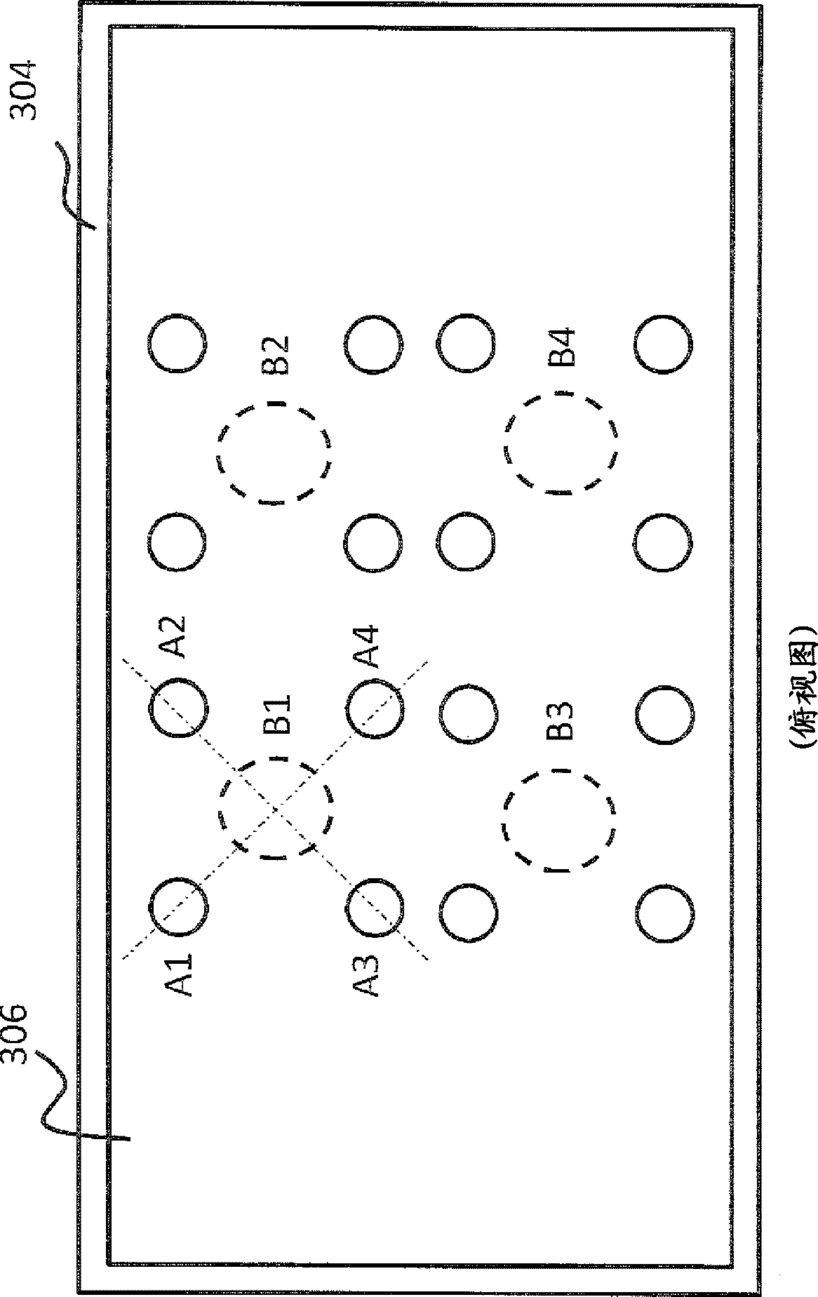
[0052] This example depicts the difference in the size of a moving bed heat exchanger when orifice plates are used, and when no orifice plates are used. The preliminary arrangement of the moving bed heat exchanger indicates that ash flow distribution and control are important to the design. The original moving bed heat exchanger design used a mass flow hopper 70 with a 70 degree angle to ensure a uniform flow of solids in the moving bed heat exchanger. shown above figure 2 , the hopper is mounted above the standpipe 112. This method requires a very tall moving bed heat exchanger, or a moving bed heat exchanger with an excessive number of hoppers and ash control valves at the bottom of the moving bed heat exchanger. Using a continuous plate with orifices reduces the gap height between the moving bed heat exchanger tube bundle and the inlet to the ash control valve by a third.

[0053] Therefore, an orifice plate system with 2 plates is formed to reduce the height requiremen...

example 2

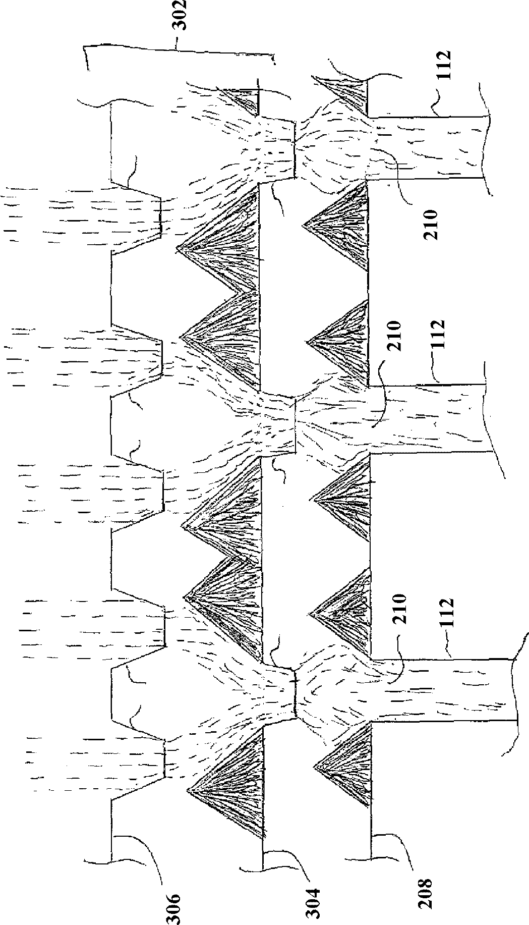
[0055] This example depicts the difference in performance between a moving bed heat exchanger without orifice plates and with orifice plates. Such as figure 1 With 4 ash control valves like the one depicted in , installed in the flat bottom area below the moving bed heat exchanger, it is expected that the ash itself will be evenly distributed over the inlet of the ash control valves at a certain angle of internal friction of solid particles representing 70 degrees. height.

[0056] The 70 degree friction angle exists for a short distance above the inlet of the ash control valve, and then the solids plume extends upward to the top, as Figure 7 as shown in the photo. There is a dead volume of ash between the plumes, which can be Figure 7 as seen in the gray areas of the . A run of the slice model without the orifice distribution plate shows that the ash flow plume extends from the top of the ash column down to the ash control valve with less spread of the plume. This ind...


PUM


Abstract

Disclosed herein is an orifice plate comprising one or more plates having orifices disposed therein; the orifices being operative to permit the flow of solids from a moving bed heat exchanger to a solids flow control system; where the orifice plate is downstream of a tube bundle of the moving bed heat exchanger and upstream of the solids flow control system and wherein the orifice plate is operative to evenly distribute the flow of solids in the solids flow control system.

Description

[0001] Cross References to Related Applications [0002] This disclosure claims U.S. Provisional Application No. 61 / 407,694, filed October 28, 2010, U.S. Provisional Application No. 61 / 407,706, filed October 28, 2010, and U.S. Provisional Application No. .61 / 407,741 of priority, the entire contents of which applications are incorporated herein by reference. [0003] Statement Regarding Federally Funded Research or Support [0004] The US Government has certain rights in this invention pursuant to Contract No. DE-FC26-OINT41223, US Department of Energy / National Energy Technology Laboratory (NETL). technical field [0005] The present disclosure relates to orifice plates for solids flow control. The present disclosure relates to orifice plates for solids flow control in moving bed heat exchangers. The present disclosure also relates to methods of using the orifice plates, and articles incorporating the orifice plates. Background technique [0006] In some thermal process...

Claims


Application Information

Patent Timeline
Patent Type & Authority Applications(China)
IPC IPC(8): F28C3/14F28F9/02
CPCF28C3/14F28D13/00F28D2021/0045F28F9/026F28F27/02
Inventor G.D.朱科拉B.C.泰金
Owner GENERAL ELECTRIC TECH GMBH
Learn More