Modularized pilotless helicopter for task loads

An unmanned helicopter and modular technology, applied in the field of unmanned aerial vehicles, can solve the problems of the limited shape and capacity of the unmanned helicopter load compartment, the complicated implementation of the external suspension method of the mission load, and the inability to apply the load equipment, so as to improve the multi-task execution. Capability, optimal flight efficiency, effect of increasing breadth

Inactive Publication Date: 2013-09-04
扬州德可达科技有限公司
View PDF6 Cites 15 Cited by
  • Summary
  • Abstract
  • Description
  • Claims
  • Application Information

AI Technical Summary

Problems solved by technology

[0004] The technical problem to be solved by the present invention is that the shape and capacity of the existing unmanned helicopter load compartment are limited, and it cannot be applied to load equipment of various types, sizes and shapes. High, fragile equipment

Method used


Image

  • Modularized pilotless helicopter for task loads
  • Modularized pilotless helicopter for task loads
  • Modularized pilotless helicopter for task loads

Examples


Embodiment 1

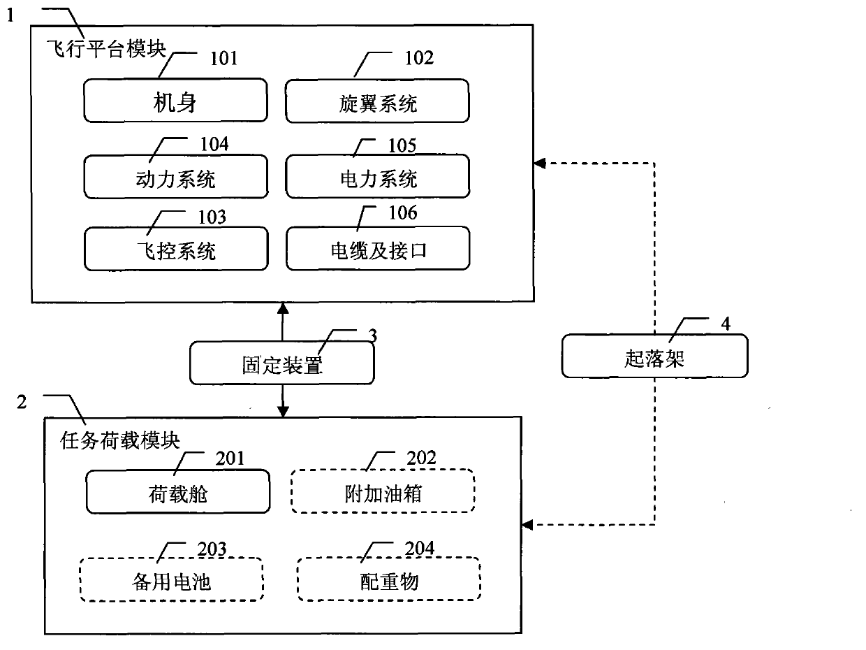
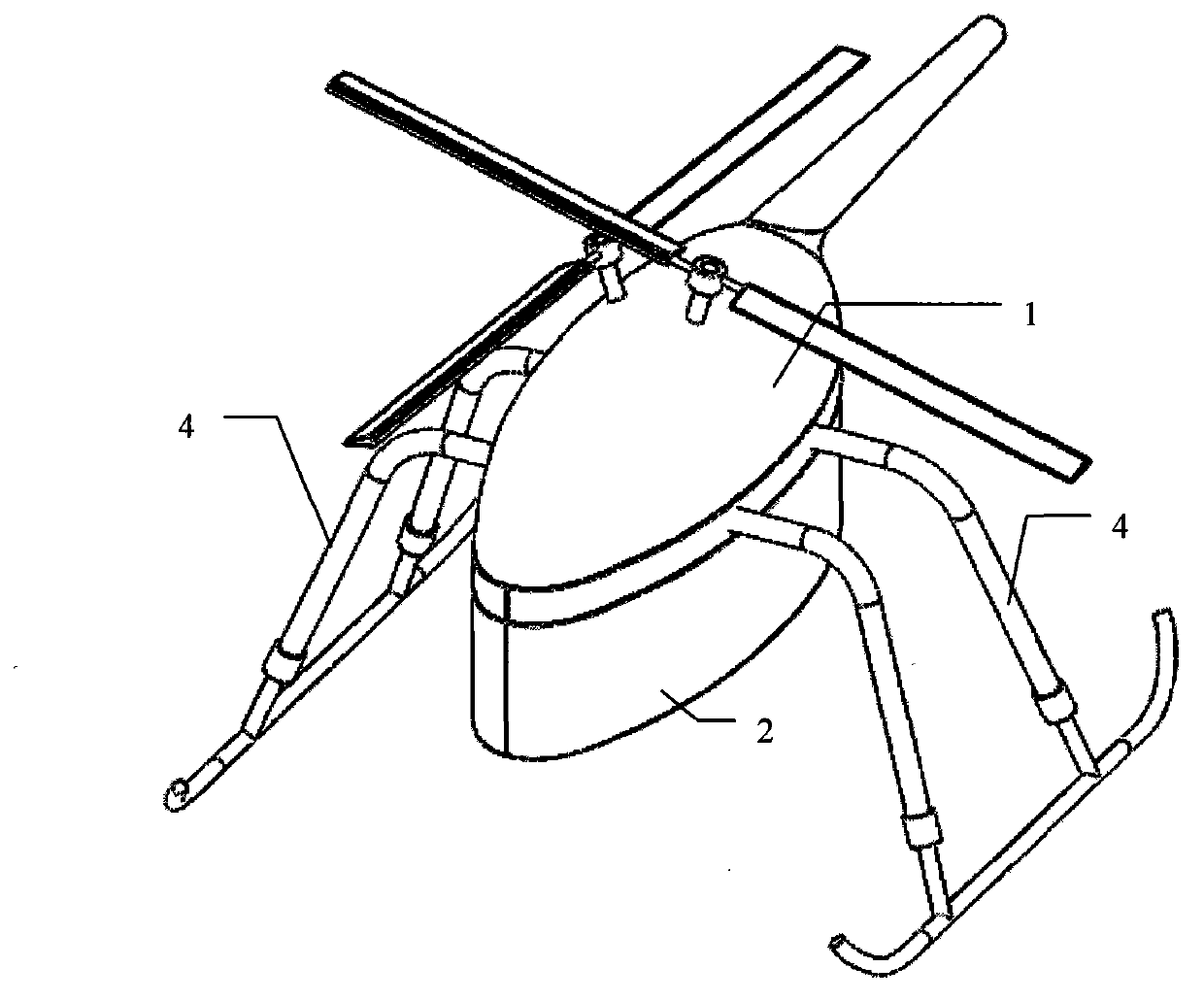
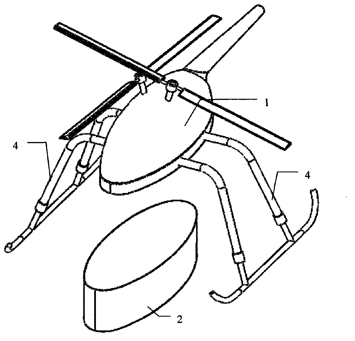
[0028] The overall structure of the unmanned helicopter is as follows: figure 2 As shown, the flight platform module 1 adopts a cross-type double-rotor rotor system 102, and the task load module 2 adopts an elliptical cabin structure. image 3 It is a schematic diagram of module decomposition. The landing gear 4 is installed on the frame of the flight platform module 1. The landing gear 4 is designed to be adjustable in height. The height of the landing gear 4 is adjusted according to the height of the task load module 2.

Embodiment 2

[0030] The overall structure of the unmanned helicopter is as follows: figure 2 As shown, the flight platform module 1 adopts a cross-type double-rotor rotor system 102, and the task load module 2 adopts an elliptical cabin structure. Figure 4 It is a schematic diagram of module decomposition. The landing gear 4 is installed on the frame of the task load module 2. The landing gear 4 is designed to be adjustable in height. The height of the landing gear 4 is adjusted according to the height of the task load module 2.

Embodiment 3

[0032] The overall structure of the unmanned helicopter is as follows: Figure 6 As shown, the flight platform module 1 is exactly the same as the flight platform module 1 in Embodiment 1, and the mission load module 2 is changed as Figure 5 The shape shown further increases the load capacity. The landing gear 4 is installed on the frame of the task load module 2 and is an adjustable height structure.

[0033] Figure 7 The flight platform module 1 in the example is a single-rotor tail rotor type, which can be used to replace the flight platform module 1 in Embodiments 1, 2 and 3 to form another unmanned helicopter.

[0034] A kind of flight platform module 1 can cooperate with multiple different task load modules 2, and likewise, a kind of task load module 2 can be used with multiple different flight platform modules 1, thereby improving the multi-function of the unmanned helicopter. task capability, broadening its scope of application.


PUM


Abstract

The invention relates to the field of pilotless helicopters, especially to a modularized pilotless helicopter for task loads. The total design of the pilotless helicopter is carried out by taking task loads as a constituent part of the pilotless helicopter. The pilotless helicopter is divided into an upper part flight platform module (1) and a lower part task load module (2); wherein the flight platform module (1) comprises regular basic components of a pilotless helicopter, the regular basic components consisting of a fuselage (101), a rotor system (102), a flight control system (103), a power system (104), a electric power system (105), cables and interfaces (106); the task load module (2) mainly consists of a load cabin (201); and the two modules are rigorous in anastomosis and firm in connection and form an integral pilotless helicopter. The problems that a conventional pilotless helicopter with a limit capacity in a singularity shape cannot be suitable for various kinds of load devices in various sizes and shapes is solved by the modularized pilotless helicopter for task loads of the invention, and the flexibility of the task load integrated usage and the multitask execution capability of the pilotless helicopter are both improved.

Description

technical field [0001] The invention relates to the field of unmanned aerial vehicles, in particular to a task load-oriented modular unmanned helicopter. Background technique [0002] In recent years, with the continuous improvement of the level of science and technology, drone technology has continued to develop. UAVs can be divided into two categories: fixed-wing and rotary-wing. The former is currently the mainstream of UAVs in the world, while the latter poses greater challenges to the design and manufacturing technology of UAVs due to its high technical content. The important difference between drones and model aircraft is that the latter only focuses on its flight performance, which is a sports and entertainment product; the former focuses on the load that can be carried and completes the specified tasks, which is a task and operating platform. Unmanned helicopters have functions such as vertical take-off and landing, hovering, low-speed and close-to-target flight, an...

Claims


Application Information

Patent Timeline
Patent Type & Authority Applications(China)
IPC IPC(8): B64C27/06B64C1/22
Inventor 唐粮
Owner 扬州德可达科技有限公司
Why Eureka
Try Eureka