Hidden type door stopper

A hidden and door suction technology, applied in the field of hidden door suction, can solve the problems of poor decorative effect, tripping, weakening effect, etc., to achieve the best use effect, avoid the use of magnets, and the effect of a flat and beautiful floor

Active Publication Date: 2013-09-04
HAOHE ENG & CONSTR
View PDF5 Cites 5 Cited by
  • Summary
  • Abstract
  • Description
  • Claims
  • Application Information

AI Technical Summary

Problems solved by technology

[0002] Door stoppers are widely used in home decoration as a tool for fixing door panels. Its function is to fix the opened door so that it will not be closed due to slight external force. The traditional door stoppers are fixed by a pair of (or the ground) and the coupling on the door panel, but when the door is required to use a push lock and open to open spaces such as corridors and lobbies due to fire escape requirements, it will generally not hit 180° due to the influence of the door closer. The door catch installed on the wall just can't meet the requirement like this, because this pair of couplers is all placed on the wall or the ground or the door panel, protrudes from the wall or the ground or the door panel, so when pedestrians walk by, accidentally At the same time, the main components and assembly screws will be exposed to the outside, and the decorative effect is poor, which affects the beauty of the indoor layout; moreover, this kind of door stopper usually adopts magnetic attraction, which will weaken the effect due to the magnetic force fading; In addition, it also hinders the operation of the cleaning device when it is necessary to clean the wall or the floor

Method used


Image

  • Hidden type door stopper
  • Hidden type door stopper
  • Hidden type door stopper

Examples


Embodiment Construction

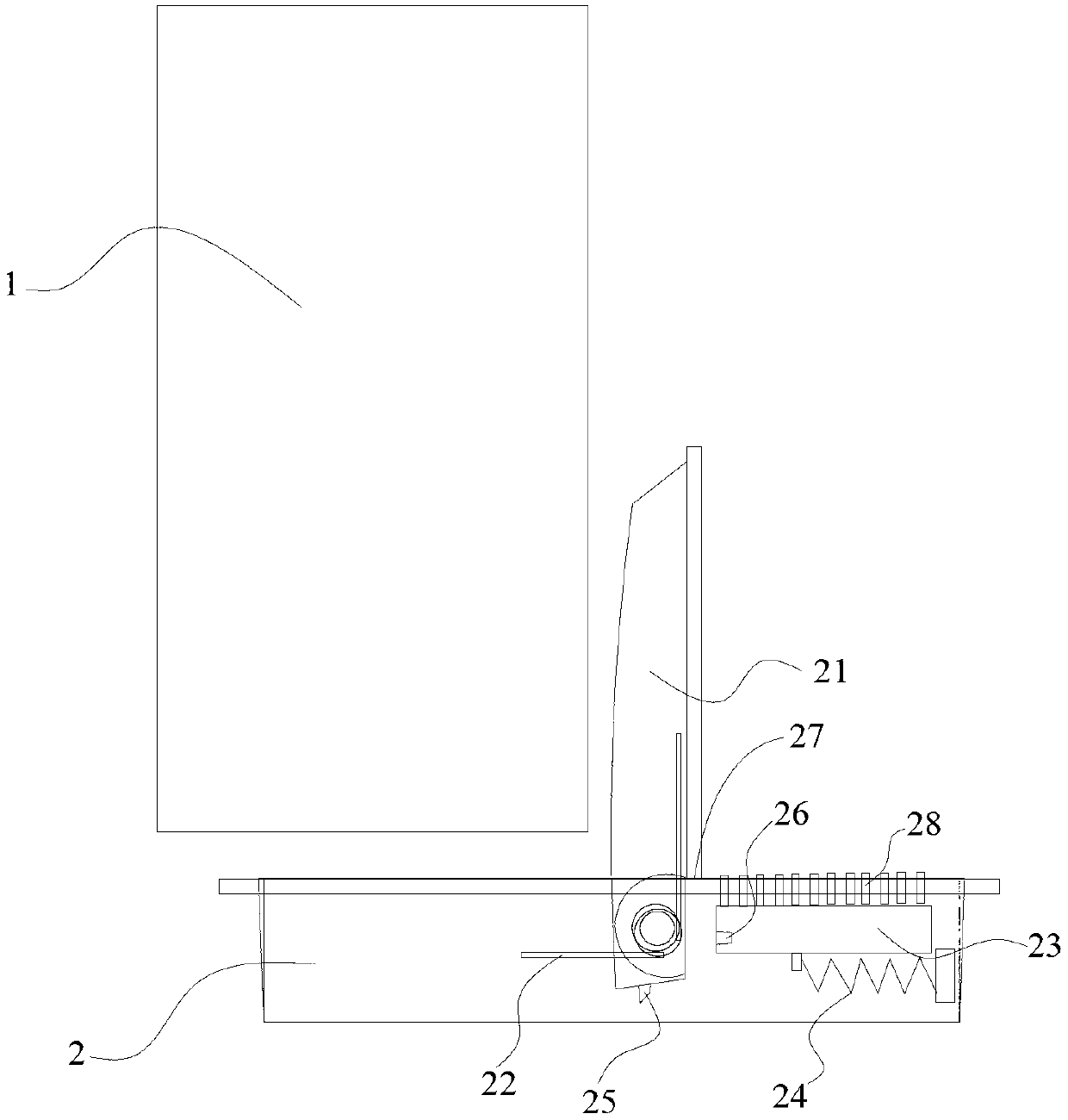
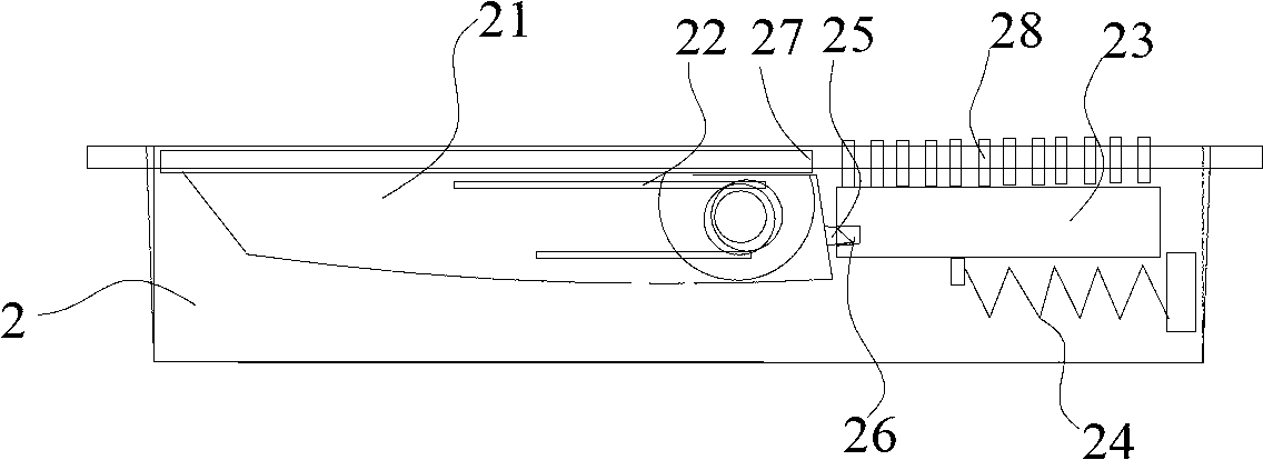
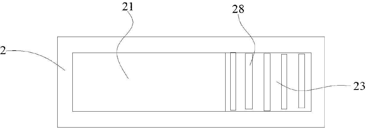
[0014] refer to Figure 1 ~ Figure 3 , the present invention provides a hidden door stopper, which includes a base 2 arranged in the ground below the door panel 1 and a stopper 21 with one end hinged in the middle of the base 2, and a stopper 21 is provided on the base 2 to make the stopper 21 bounce around the hinge point. The elastic member 22 and the base 2 are provided with a slide block 23 behind the stop block 21 that can slide forward and backward, and the rear end surface of the stop block 21 and the slide block 23 are provided with buckles that engage with each other.

[0015] This hidden door stopper is embedded in the ground according to the planned opening range of the door panel 1. The stopper 21 usually lies flat on the base 2. When it is necessary to use it, open the door panel 1 to the back of the door stopper and push the slider 23. The stopper 21 is on the elastic part 22. It bounces up under the action of the door panel 1 and blocks the inner side of the doo...


PUM


Abstract

The invention discloses a hidden type door stopper which is used for the field of parts of a door and a window. The hidden type door stopper comprises a base arranged in the floor under a door plate, and a check block, wherein one end of the check block is articulated in the middle of the base; the base is provided with an elastic piece used for enabling the check block to bounce around a hinge point; a sliding block capable of sliding front and back is arranged at the rear of the check block in the base; and buckles which are buckled with each other are arranged between the end surface of the rear side of the check block and the sliding block. The hidden type door stopper is embedded into the floor according to the planned opening amplitude of the door plate; the check block flatly lies in the base at ordinary times, the door plate is opened to the rear part of the door stopper when the check block is used, the sliding block is pushed, and the check block bounces under the action of the elastic piece and blocks on the inner side of the door plate, so that the door plate is prevented from being closed; when the door needs to be closed, the door plate is slightly pushed, and the check block is pressed and is buckled with the sliding block, so that the door plate is smoothly closed. By adopting the hidden design that the door stopper is embedded into the floor, the hidden type door stopper does not influence the pedestrian safety, guarantees the floor to be flat and attractive, and avoids the use of magnet, so that effect weakening caused by magnetism fading can not occur, and a good using effect is further achieved.

Description

technical field [0001] The invention relates to a door accessory, in particular to a hidden door stopper. Background technique [0002] Door stoppers are widely used in home decoration as a tool for fixing door panels. Its function is to fix the opened door so that it will not be closed due to slight external force. The traditional door stoppers are fixed by a pair of (or the ground) and the coupling on the door panel, but when the door is required to use a push lock and open to open spaces such as corridors and lobbies due to fire escape requirements, it will generally not hit 180° due to the influence of the door closer. The door catch installed on the wall just can't meet the requirement like this, because this pair of couplers is all placed on the wall or the ground or the door panel, protrudes from the wall or the ground or the door panel, so when pedestrians walk by, accidentally At the same time, the main components and assembly screws will be exposed to the outside,...

Claims


Application Information

Patent Timeline
IPC IPC(8): E05C17/02
Inventor 刘晗晨周岳杨光田勇马绍腾
Owner HAOHE ENG & CONSTR
Why Eureka
Try Eureka