A lithium-air battery mold

An air battery and mold technology, applied in the direction of fuel cell half-cells and primary battery-type half-cells, can solve the problems of complex components, poor battery space utilization, cumbersome assembly/disassembly process, etc., to achieve simple components, High space utilization and the effect of improving space utilization

Active Publication Date: 2016-01-13
CHANGCHUN INST OF APPLIED CHEMISTRY - CHINESE ACAD OF SCI
View PDF7 Cites 0 Cited by
  • Summary
  • Abstract
  • Description
  • Claims
  • Application Information

AI Technical Summary

Problems solved by technology

[0003] In order to solve the technical problems of complex components of the existing lithium-air battery mold components, cumbersome assembly / disassembly process and poor battery space utilization rate, the present invention provides a mold with simple components, compact structure, convenient assembly / disassembly, and high battery space utilization rate. Lithium-air battery mold

Method used


Image

  • A lithium-air battery mold
  • A lithium-air battery mold
  • A lithium-air battery mold

Examples


Embodiment 1

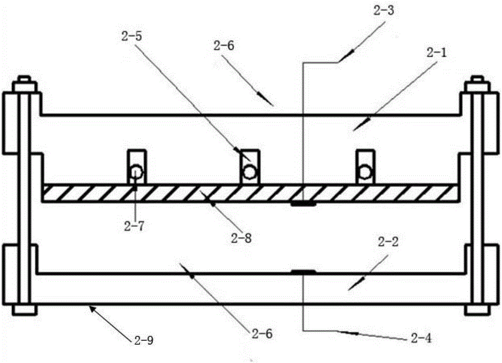
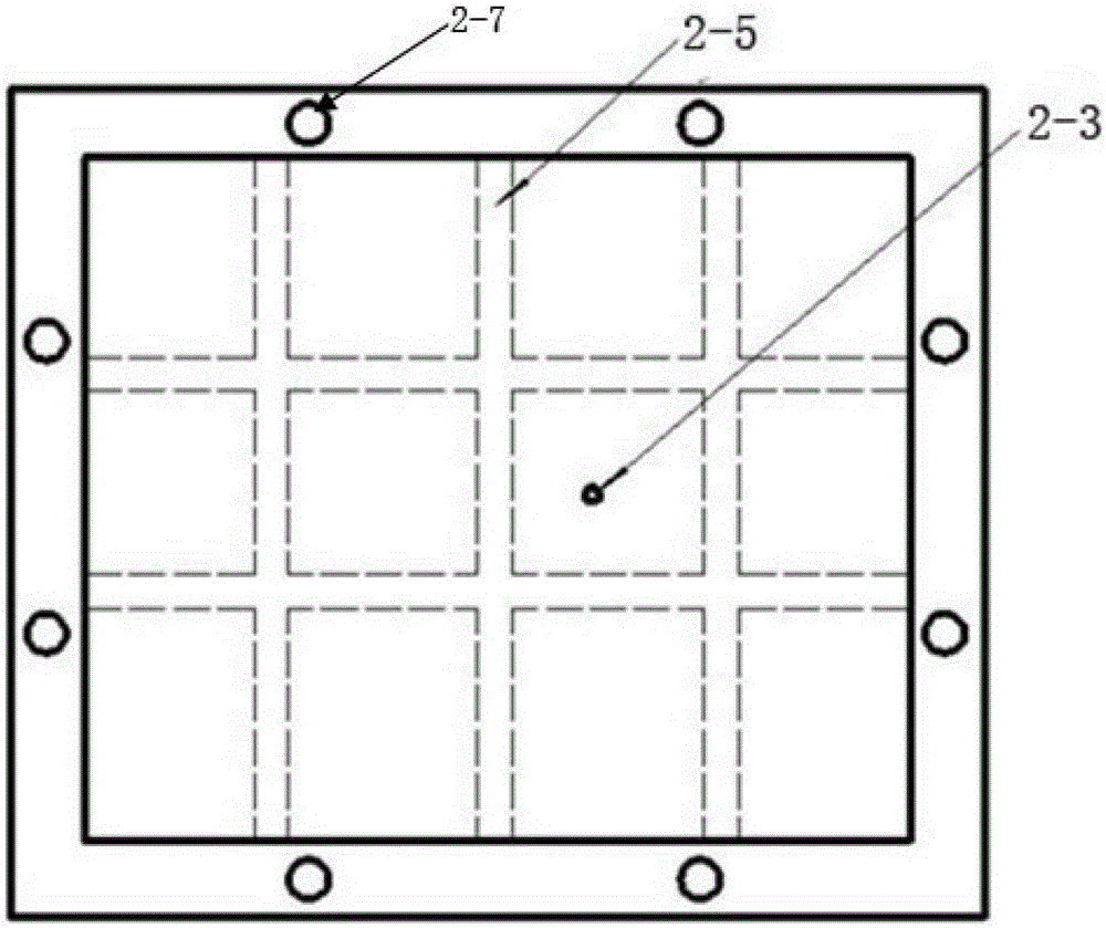
[0040] The assembly shell 2-1 and the base shell 2-2 are made of polytetrafluoroethylene, and the size is 100×100mm 2 .

[0041] The assembly process of the lithium-air battery is completed in the glove box. The process is as follows: the negative electrode of the lithium sheet is placed in the groove 2-6 on the base shell 2-2, the diaphragm is placed on the negative electrode of the lithium sheet, and an appropriate amount of electrolytic solution is dripped on the diaphragm. solution, place the air positive electrode on the diaphragm dripped with electrolyte, drop an appropriate amount of electrolyte on the air positive electrode, place a current collector on the air positive electrode dripped with electrolyte, then put it into the assembly shell 2-1, and finally pass the rotating Tighten the bolts to secure the battery case. Place the assembled cells in an air or oxygen atmosphere, and connect the test circuit to test the performance of the cells. Place the assembled cell...

Embodiment 2

[0044] The two assembled shells 2-1 and the base shell 2-2 are made of polypropylene material, and the area of ​​the assembled shell 2-1 and the base shell 2-2 is 100×200mm 2 . Brass materials are used as the positive electrode lead 2-3 and the negative electrode lead 2-4.

[0045]The assembly process of the lithium-air secondary battery pack is completed in the glove box, the negative electrode of the lithium sheet is placed in the groove 2-6 on the base shell 2-2, the diaphragm is placed on the negative electrode of the lithium sheet, and an appropriate amount of electrolyte is dripped on the diaphragm, Place the air positive electrode on the diaphragm dripped with electrolyte, drop an appropriate amount of electrolyte on the air positive electrode, place a current collector on the air positive electrode dripped with electrolyte, and then put it into the assembly case 2-1, and then put another lithium The negative electrode of the lithium sheet is placed in the groove 2-6 o...


PUM


Abstract

The invention relates to a lithium-air battery mold, which solves the technical problems that the components of the existing lithium-air battery mold are complicated, the assembly / dismounting process is complicated, and the space utilization rate is poor. The lithium-air battery mold mainly comprises an assembly casing and a base casing, wherein the lower end of the assembly casing is suitable for being arranged in a groove of another assembly casing or a groove formed at the upper end of the base casing, and a groove formed at the upper end of the assembly casing and the groove formed at the upper end of the base casing are suitable for placing lithium-air battery modules. The mold adopting the structural design is used for manufacturing lithium-air batteries, the weight of the batteries can be favorably reduced, and the space utilization rate of the batteries and the energy density of the batteries can be improved. The lithium-air secondary battery mold provided by the invention has the advantages that the structure is compact, the assembly is convenient, the lithium-air secondary battery mold can be widely used for the basic and application study of lithium-air secondary batteries. The lithium-air secondary battery comprising the battery mold has higher energy density and longer cycle life.

Description

technical field [0001] The invention belongs to the technical field of chemical power sources, in particular to a lithium-air battery mold. Background technique [0002] At present, most of the molds used in lithium-air battery research can meet the needs of basic research on lithium-air batteries to a certain extent, but they all have certain defects, such as inability to completely discharge argon, rapid evaporation of electrolyte, and airflow. interference etc. An announcement dated December 26, 2012 by Shanghai Jiaotong University, a utility model patent with a publication number of CN2026317131710, discloses a lithium-air battery mold, which solves the above problems. Such as figure 1 As shown, the lithium-air battery mold mainly includes a positive electrode casing 1-1, a detachable air inlet channel 1-2, a detachable air outlet channel 1-4, an insulating casing 1-5, and a negative electrode casing 1-6. , Positive lead terminal 1-9, negative lead terminal 1-10. The...

Claims


Application Information

Patent Timeline
Patent Type & Authority Patents(China)
IPC IPC(8): H01M12/06
Inventor 张新波徐吉静刘清朝常志文尹彦斌
Owner CHANGCHUN INST OF APPLIED CHEMISTRY - CHINESE ACAD OF SCI
Why Eureka
Try Eureka