
Reclosing mechanism of residual-current circuit breaker

A leakage circuit breaker and reclosing technology, applied in the direction of protection switch operation/release mechanism, etc., can solve the problems of inability to install the whole circuit breaker, increase the size of the circuit breaker, increase the production cost, etc., so as to improve the service life, improve the production efficiency, The effect of reducing the difficulty of installation

Active Publication Date: 2015-01-28
EATON HUINENG LOW-VOLTAGE ELECTRICAL (JIANGSU) CO LTD
View PDF4 Cites 0 Cited by
  • Summary
  • Abstract
  • Description
  • Claims
  • Application Information

AI Technical Summary

Problems solved by technology

At present, the existing automatic reclosing mechanism of molded case circuit breaker consists of a handle, at least two large and small gears, a number of stamping parts and a number of standard rooms. After the switch is closed, the handle driver on the reclosing mechanism is linked with the handle, and the handle cannot be moved manually.
This kind of reclosing mechanism has the following problems: 1. Due to the gear structure, the height of the mechanism is high, which increases the volume of the circuit breaker; and the gear processing is difficult, the efficiency is relatively low, and the production cost is increased.
2. During installation, the component parts are not an integral structure, and cannot be installed as a set of components as a whole, and each circuit breaker mechanism needs to be adjusted; 3. A rigid connection is formed between the reclosing mechanism and the handle, and the handle does not have indication opening, Function of the tripped position

Method used


Image

  • Reclosing mechanism of residual-current circuit breaker
  • Reclosing mechanism of residual-current circuit breaker
  • Reclosing mechanism of residual-current circuit breaker

Examples


Embodiment Construction

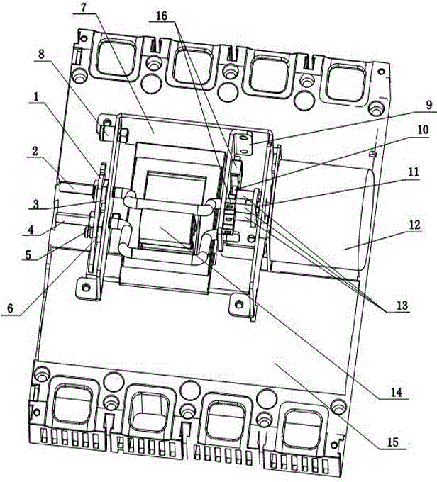
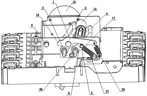
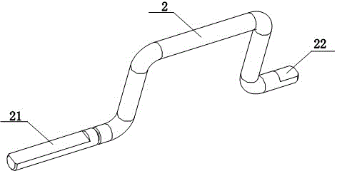
[0024] Such as figure 1 with figure 2 As shown, the present invention includes an outer frame 7, an inner bracket 9, a connecting rod, a turntable, two handle drivers, etc., and the outer frame 7 is fixedly mounted on a circuit breaker cover 15 with a handle 14, and the handle 14 extends out of the circuit breaker Outside the cover 15, the handle 14 can be rotated towards the wire inlet or outlet of the circuit breaker. The handle 14 is located between the two handle drive parts, and the two handle drive parts are respectively located at the wire-in end and the wire-out end side of the handle 14, that is, the first handle drive part 2 can be located at the wire-in end side of the handle 14, and the second handle drive The piece 4 can be located at the outlet end side of the handle 14 . The inner bracket 9 is fixedly installed in the outer frame 7 . The first turntable 10 is rotatably connected to the inner bracket 9, and the rotation direction of the first turntable 10 is ...


PUM


Abstract

The invention discloses a reclosing mechanism of a residual-current circuit breaker. The reclosing mechanism of the residual-current circuit breaker is provided with an outer frame, wherein the outer frame is fixedly arranged on a circuit breaker outer cover with a handle. The wire inlet end and the wire outlet end of the handle are respectively provided with a handle drive piece. One end of each handle drive piece penetrates through a lateral wall of the outer frame in a clearance mode and stretches outside. The other end, located on the handle wire inlet end side, of a first handle drive piece is coaxially and fixedly connected with a first rotating disc, and the first rotating disc is connected with a motor in a rigid mode. One end of the first handle drive piece is connected with one end of a rotating piece through a first connection rod, and the other end of the rotating piece is connected with a second reset spring ensuring that the rotating piece rotates towards the direction of the wire outlet end. A second handle drive piece is connected with one end of a second connection rod, and the other end of the second connection rod is provided with a protruded rivet shaft and is connected with a first reset spring ensuring that the second connection rod rotates towards the direction of the wire outlet end. A handle is driven by handle drive pieces to open or close the circuit breaker. After the circuit breaker is closed, the two handle drive pieces are respectively located outside the operating range of the handle, and the working state is still indicated by the handle.

Description

technical field [0001] The invention relates to a molded case circuit breaker with residual current protection in the field of low-voltage electrical technology, in particular to a reclosing operating mechanism of a leakage molded case circuit breaker with an automatic reclosing function. Background technique [0002] The leakage molded case circuit breaker with automatic reclosing function can ensure the continuous, safe and reliable operation of the power system. At present, the existing automatic reclosing mechanism of molded case circuit breaker consists of a handle, at least two large and small gears, a number of stamping parts and a number of standard rooms. After the switch is closed, the handle driver on the reclosing mechanism is linked with the handle, and the handle cannot be moved manually. This reclosing mechanism has the following problems: 1. Due to the gear structure, the height of the mechanism is high, which increases the volume of the circuit breaker; and...

Claims


Application Information

Patent Timeline
Patent Type & Authority Patents(China)
IPC IPC(8): H01H71/10
Inventor 陈咸任飞胡义琴李冰燕
Owner EATON HUINENG LOW-VOLTAGE ELECTRICAL (JIANGSU) CO LTD
Learn More