Thumb structure of prosthetic hand

A prosthetic hand and thumb technology, applied in prosthesis, medical science, etc., can solve the problems of heavy weight, insufficient flexibility, too many drives, etc., and achieve the effect of strong self-adaptive ability

Active Publication Date: 2013-09-11
HUAZHONG UNIV OF SCI & TECH
View PDF5 Cites 17 Cited by
  • Summary
  • Abstract
  • Description
  • Claims
  • Application Information

AI Technical Summary

Problems solved by technology

[0003] The invention provides a thumb mechanism of a prosthetic hand, which solves the problems of too many driving numbers, too heavy weight and insufficient flexibility of the existing thumb mechanism of a prosthetic hand

Method used


Image

  • Thumb structure of prosthetic hand
  • Thumb structure of prosthetic hand
  • Thumb structure of prosthetic hand

Examples


Embodiment Construction

[0027] The present invention will be further described below in conjunction with the accompanying drawings and embodiments.

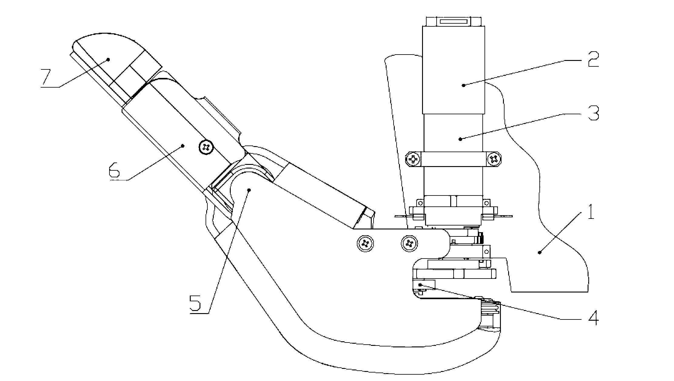
[0028] Such as figure 1 As shown, the present embodiment includes a palm base plate 1, a servo motor 2, a speed reducer 3, a transmission mechanism 4, a near knuckle 5, a middle knuckle 6 and a far knuckle 7; the servo motor 2 and the speed reducer 3 are fixed on the palm base plate 1, the servo motor 2 is connected to the reducer 3, the reducer 3 is connected to the transmission mechanism 4, the transmission mechanism 4 is connected to the proximal knuckle 5, and the proximal knuckle 5, middle knuckle 6 and distal knuckle 7 are connected in turn in rotation.

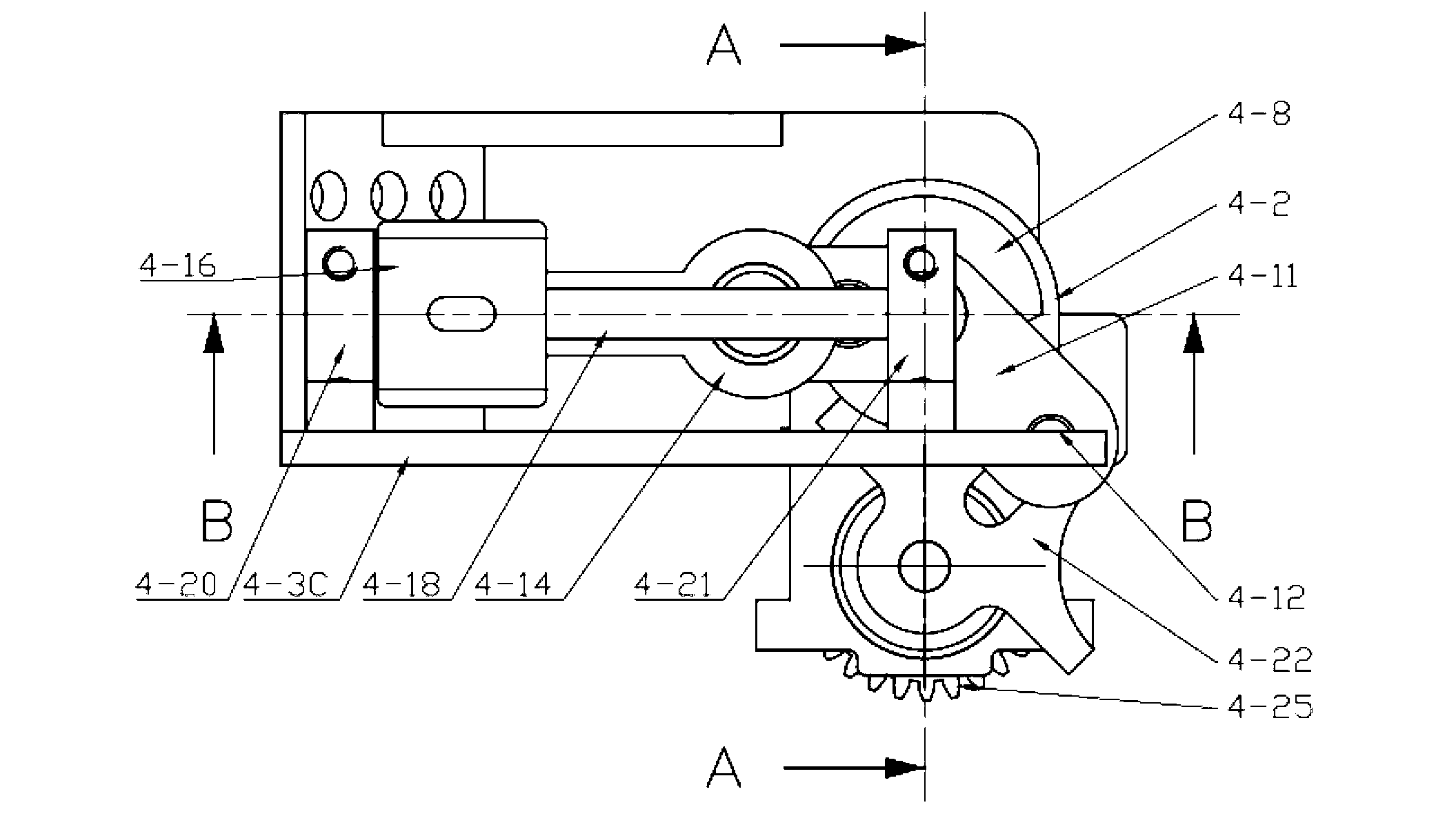
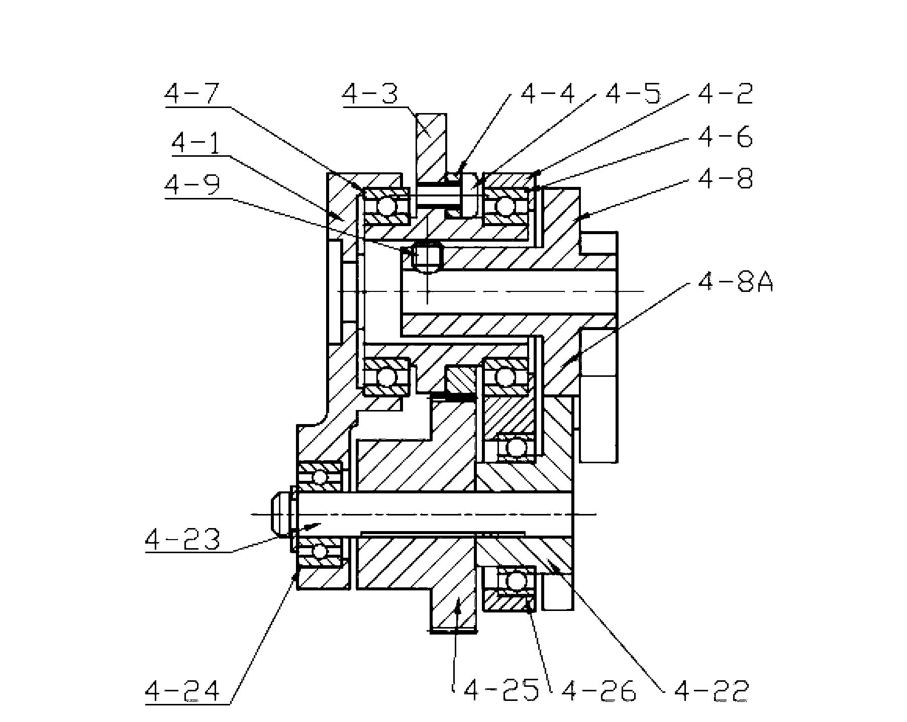
[0029] Such as figure 2 , image 3 , Figure 4 As shown, the transmission mechanism 4 includes a motor support plate 4-1, a sheave support plate 4-2, a thumb base 4-3, a driven gear 4-4, a round head screw 4-5, a first ball roller Sub-bearing 4-6, second ball roller bearing 4-7, driving dial...


PUM


Abstract

The invention discloses a thumb structure of a prosthetic hand and belongs to the field of medical apparatuses. The thumb structure of the prosthetic hand solves the problems that an existing thumb structure of the prosthetic hand is excessive in drives, heavy and insufficient in flexibility. The thumb structure of the prosthetic hand comprises a palm bottom plate, a servo motor, a speed reducer, transmission mechanism a near knuckle, a middle knuckle and a far knuckle, the servo motor and the speed reducer which are mutually connected are fixed on the palm bottom plate, the speed reducer is connected with the transmission mechanism which is connected with the near knuckle, and the near knuckle, the middle knuckle and the far knuckle are rotationally connected sequentially. The thumb structure of the prosthetic hand adopts the servo motor to drive a thumb to bend and laterally swing, has three degrees of freedom, is extremely similar to a human thumb in shape and moving mode, and is attractive in appearance, human simulated and practical. Experimental results show that the thumb structure of the prosthetic hand has great self-adaptive capability when matches with other fingers during gripping and can realize enveloping, precise gripping, powerful gripping and side nipping of complex objects.

Description

technical field [0001] The invention belongs to the field of medical equipment, and in particular relates to a thumb mechanism of a prosthetic hand. Background technique [0002] At present, the KNU prosthetic hand in South Korea adopts an external grooved wheel mechanism, and its fingers are driven by a connecting rod, and the connecting rod fingers have the defect that the structure is not compact (see Jun-Uk Chu, Dong-Hyun Jung and Yun-Jung Lee, Design and Control of a Multifunction Myoelectric Hand with New Adaptive Grasping and Self-locking Mechanisms, in2008IEEE International Conference on Robotics and Automation.2008: Pasadena, CA, USA); the MANUS prosthetic hand also uses a sheave mechanism, but the drive that transmits the motor power The path is too complicated, and the energy loss of the transmission chain is too large (see J.L.PONS, E.ROCON and R.CERES. The MANUS-HAND Dextrous robotics upper limb prosthesis: Mechanical and manipulation aspects. Autonomous Robots,...

Claims


Application Information

Patent Timeline
Patent Type & Authority Applications(China)
IPC IPC(8): A61F2/56
Inventor 熊蔡华张可科陈慧龙熊有伦翟明春
Owner HUAZHONG UNIV OF SCI & TECH
Why Eureka
Try Eureka