Metal band sawing machine for cutting slice wind-power flange

A technology for wind power flanges and metal strips, which is applied in metal sawing equipment, sawing machine devices, metal processing equipment, etc., and can solve the problem that the workbench cannot move horizontally and the power head cannot move horizontally. Cutting and other issues, to achieve the effect of simple structure, low cost and high product qualification rate

Active Publication Date: 2013-09-11
SHANXI TIANBAO GRP CO LTD +1
View PDF6 Cites 5 Cited by
  • Summary
  • Abstract
  • Description
  • Claims
  • Application Information

AI Technical Summary

Problems solved by technology

But the current sawing machine can't cut the double forgings of the thin-section wind power flange, and there are deficiencies. The disadvantages are: the power head of the sawing machine carrying the saw blade cannot be horizontally moved and cut; the worktable of the sawing machine carrying the workpiece cannot Horizontal translation feed feeding

Method used


Image

  • Metal band sawing machine for cutting slice wind-power flange
  • Metal band sawing machine for cutting slice wind-power flange
  • Metal band sawing machine for cutting slice wind-power flange

Examples


Embodiment 1

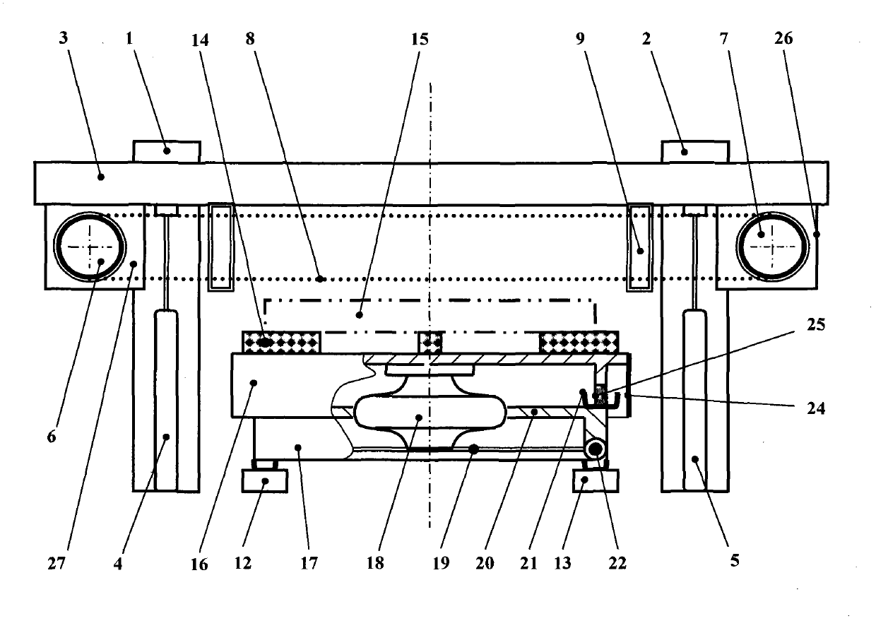
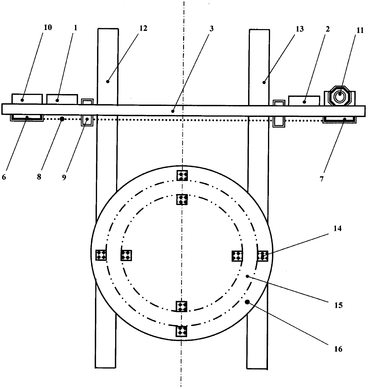
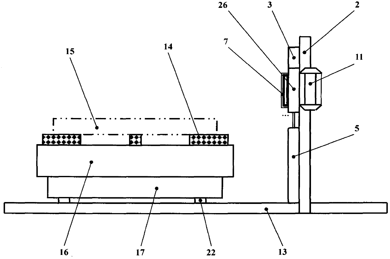
[0024] exist figure 1 figure 2 image 3 In the first embodiment shown, a metal band sawing machine for cutting flake wind power flanges includes vertical gantry columns 1 and 2 with rectangular cross-sections and upper horizontal cross-sections in front of gantry columns 1 and 2. The gantry frame formed by the rectangular moving beam 3, and below the moving beam 3 between the gantry columns 1 and 2 tops, guide rails 12, 13 that are vertical to the gantry columns 1, 2 and the moving beam 3 are horizontally arranged. The two ends of the guide rails 12, 13 are linearly extended, and its characteristics are: sliding connection between the vertical gantry columns 1, 2 and the horizontal moving beam 3, and the lower part of the moving beam 3 in front of the gantry columns 1, 2 is connected with Hydraulic support column 4, 5;

[0025] The bottom of the left end of the moving crossbeam 3 is provided with a rectangular plate-type driven support seat 27 near the left side of the gan...


PUM


Abstract

The invention discloses a metal band sawing machine for cutting a slice wind-power flange, and belongs to the technical field of mechanical equipment. A saw band carried by the sawing machine can perform horizontal cutting, and a carried workpiece table can move horizontally for feeding. The key points of the technical scheme are that the metal band sawing machine comprises a gantry framework, wherein the gantry framework is formed by vertically arranged gantry columns (1 and 2) with rectangular cross sections, as well as a movable cross beam (3) which is transversely placed at the upper part in the front and provided with a rectangular cross section; guide rails (12 and 13) are arranged below the movable cross beam (3) between the gantry columns (1 and 2); and a cylindrical moveable workpiece platform is arranged on the guide rails (12 and 13). The metal band sawing machine can achieve cutting of the slice wind-power flange by the disc saw band (8), and is simple in structure.

Description

【Technical field】 [0001] The invention belongs to the technical field of mechanical equipment. In particular, it relates to a device for sawing and blanking metal bars or metal pipes. 【Background technique】 [0002] At present, smaller-sized wind power flanges are formed by heating and forging metal blanks into metal forgings, and then heat-treating and machine-cutting. For larger-sized wind power flange parts, the metal billet is heated and forged into a metal forging, and then heat-treated and machine-cut. However, the warping deformation of the upper and lower surfaces of the larger-sized wind power flange is serious during heating and forging, and the deformation of the upper and lower surfaces and the aperture is serious during heat treatment. Often, the internal mechanical parts of the metal are damaged due to uneven stress during the unavoidable shaping process. The product is scrapped due to uneven strength. Therefore, in order to reduce or avoid the shaping proce...

Claims


Application Information

Patent Timeline
IPC IPC(8): B23D53/06B23D55/02B23D55/04
Inventor 胡全喜闫满红吴昊路峰易莉段二顺张雁玲李耀龙樊璟赟郭焕平
Owner SHANXI TIANBAO GRP CO LTD
Why Eureka
Try Eureka