Laser engraving machine and operating method thereof

A laser engraving machine and visual positioning technology, applied in welding equipment, laser welding equipment, metal processing equipment, etc., can solve the problems of low positioning accuracy of parts, unsuitable for diversified production, low utilization rate of laser engraving machines, etc., to achieve Improve the utilization rate, improve the quality and product qualification rate, and protect the effect of safety

Active Publication Date: 2015-09-09
JIANGSU CHUANGYUAN ELECTRON CO LTD
View PDF7 Cites 14 Cited by
  • Summary
  • Abstract
  • Description
  • Claims
  • Application Information

AI Technical Summary

Problems solved by technology

[0003] The laser engraving machine in the prior art, including the visual positioning system and the laser engraving machine system group, is only equipped with a material carrier for a certain type of part, and can only be used for laser engraving of specific parts, and the utilization rate of the laser engraving machine is low. , for each type of laser engraving parts, it is necessary to purchase different laser engraving machines, which will greatly increase the cost of the factory and is not suitable for diversified production
[0004] In addition, the laser engraving machine in the prior art does not have high positioning accuracy for the parts. During the laser engraving process, the parts will become loose. The quality of the product after laser engraving is low, and the product qualification rate is low.

Method used


Image

  • Laser engraving machine and operating method thereof
  • Laser engraving machine and operating method thereof
  • Laser engraving machine and operating method thereof

Examples


Embodiment Construction

[0035] In order to make the above objects, features and advantages of the present invention more comprehensible, specific implementations of the present invention will be described in detail below in conjunction with the accompanying drawings.

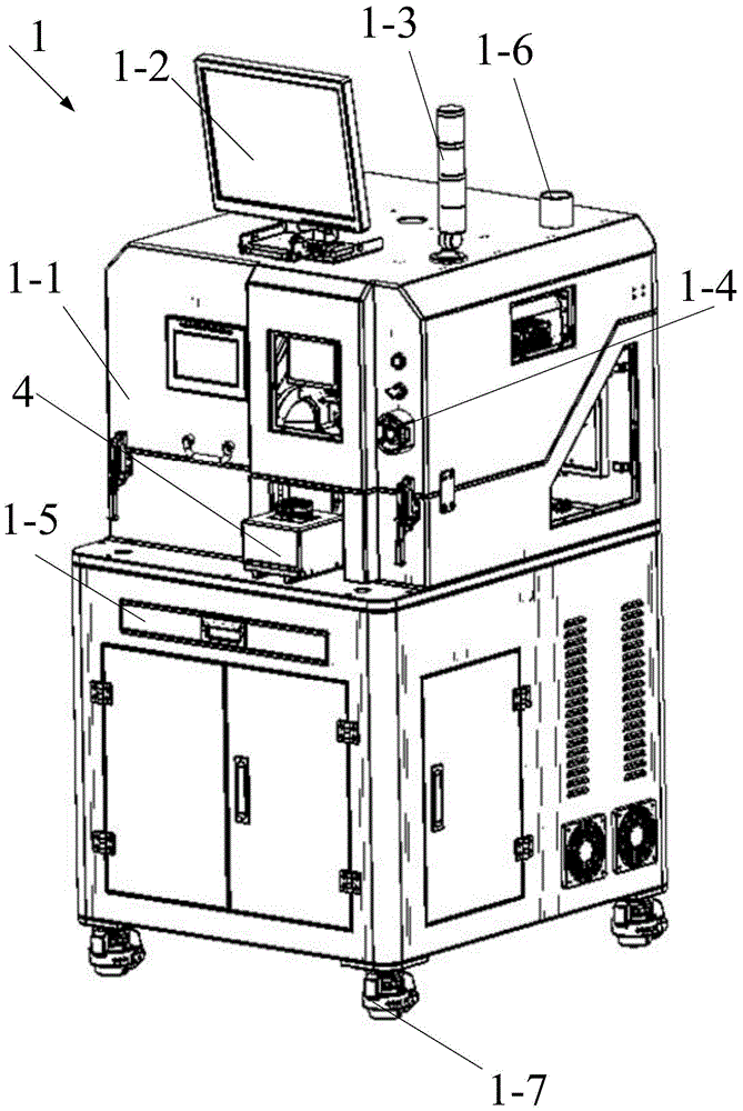
[0036] Please refer to Figure 1a and Figure 1b , a laser engraving machine, comprising a box 1,

[0037] AC voltage stabilizer, after the power is turned on, the AC voltage stabilizer can provide a stable voltage for the laser engraving machine;

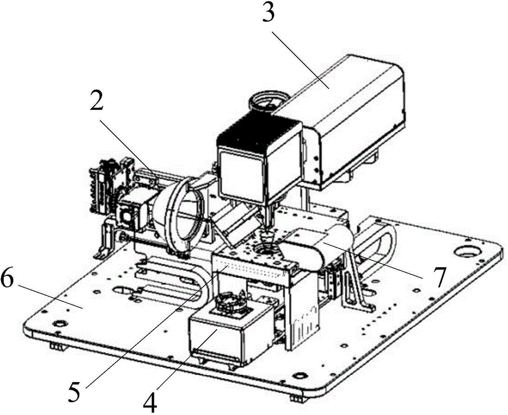
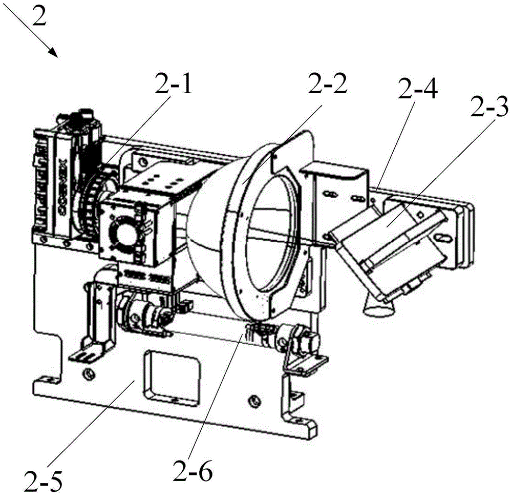
[0038] Visual positioning system 2, said visual positioning system 2 is slidably connected with the visual positioning system motion guide rail arranged on said support platform 6, and said visual positioning system makes X along the visual positioning system motion guide rail on said support platform 6 direction movement; visual positioning system 2 is used to take pictures and locate the parts to be processed;

[0039] The height-adjustable laser engraving machine system 3 is used for l...


PUM


Abstract

The invention discloses a laser engraving machine which comprises a box body, an alternating-current voltage stabilizer, a visual positioning system, a laser engraving machine system, a pre-positioning module, a correction module, a safety system, a supporting table, an exhaust system and a control system. The visual positioning system is in sliding connection with a visual positioning system motion guide rail on the supporting table, and the visual positioning system does X-direction motion along the visual positioning system motion guide rail on the supporting table. The correction module is fixed to the position, below the laser engraving machine system, of the supporting table. The pre-positioning module is arranged below the correction module, and is in sliding connection with a pre-positioning module motion guide rail on the supporting table. The pre-positioning module does Y-direction motion along the pre-positioning module motion guide rail. The invention further discloses an operating method of the laser engraving machine. The pre-positioning module and the correction module of the laser engraving machine can be replaced with different pre-positioning modules and correction modules, laser engraving on different parts is achieved, the utilization rate of the laser engraving machine is improved, the cost of factories is saved, and the application range is wide.

Description

technical field [0001] The invention relates to a laser engraving machine and an operation method of the laser engraving machine. Background technique [0002] Laser engraving, also known as laser engraving or laser marking, is a surface treatment process that uses optical principles. It uses high-intensity focused laser beams emitted by lasers at the focal point to evaporate surface substances to expose deep substances; or through light energy. The chemical and physical changes of the surface material produce traces; or burn off part of the material through light energy, and "carve" traces; or burn part of the material through light energy, showing the graphics and characters that need to be etched. [0003] The laser engraving machine in the prior art, including the visual positioning system and the laser engraving machine system group, is only equipped with a material carrier for a certain type of part, and can only be used for laser engraving of specific parts, and the u...

Claims


Application Information

Patent Timeline
Patent Type & Authority Applications(China)
IPC IPC(8): B23K26/362B23K26/16B23K26/70
CPCB23K26/16
Inventor 楚佳
Owner JIANGSU CHUANGYUAN ELECTRON CO LTD
Why Eureka
Try Eureka