
Cooling cover of welding equipment

A welding equipment and connection position technology, applied in welding equipment, auxiliary welding equipment, welding/cutting auxiliary equipment, etc., can solve the problem of ineffective heat dissipation of the welding machine, and achieve convenient hoisting, uniform cooling, and balanced intake and exhaust. Effect

Active Publication Date: 2015-04-15
重庆西南铝铝材生产开发股份有限公司
View PDF9 Cites 0 Cited by
  • Summary
  • Abstract
  • Description
  • Claims
  • Application Information

AI Technical Summary

Problems solved by technology

[0005] The purpose of the present invention is to overcome the deficiency that the prior art cannot effectively dissipate heat to the welding machine, and to provide a welding equipment cooling cover for the welding machine

Method used


Image

  • Cooling cover of welding equipment
  • Cooling cover of welding equipment

Examples


Embodiment 1

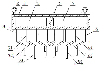
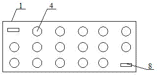
[0031] Such as figure 1 with figure 2 The cooling cover of the welding equipment shown includes a cover body 1, a first fan 2 and a plurality of exhaust pipes 3, the first fan 2 is arranged in the cover body 1, and the exhaust pipe 3 is arranged at the bottom of the cover body 1 and connected to the inside of the cover body 1 The space is connected, the connection position between the air extraction pipe 3 and the cover body 1 is located within the range of the first fan 2, the top of the cover body 1 is provided with an air hole 4, and the lengths of the plurality of air extraction pipes 3 are different.

[0032] When in use, this embodiment is arranged on the top of the welding machine. The exhaust pipe 3 extends into the inside of the welding machine, and the high-temperature air inside the welding machine is extracted by the first fan 2 to achieve the purpose of cooling the welding machine. The exhaust pipes 3 with different lengths can extend into positions of differen...


PUM


Abstract

The invention discloses a cooling cover of welding equipment. The cooling cover comprises a cover body, a first fan and a plurality of air extracting tubes. The first fan is arranged in the cover body, the air extracting tubes are arranged at the bottom of the cover body and communicated with inner space of the cover body, connecting positions of the air extracting tubes and the cover body are within the range of the first fan, an air hole is formed at the top of the cover body, and the air extracting tubes have different lengths. The cooling cover has the advantages that the air extracting tubes extend into the inner portion of a welding machine, and the first fan is used for extracting high-temperature air inside the welding machine, so that cooling of the welding machine can be realized; the air extracting tubes with the different lengths can extend to positions with different heights inside the welding machine, so that cooling of the positions with the different heights inside the welding machine can be realized. The cooling cover can actively extract the high-temperature air inside the welding machine, active cooling is realized and cooling efficiency is high.

Description

technical field [0001] The invention relates to the field of welding equipment, in particular to a cooling cover for welding equipment. Background technique [0002] The welding machine will generate high temperature and high heat during operation. If the generated heat cannot be dissipated in time, it will seriously affect the normal operation of the equipment, and even bring safety hazards. Therefore, it is necessary to dissipate heat from the welding machine. [0003] Existing welding machines realize the natural dissipation of heat therein by opening holes in the welding machine casing. However, this heat dissipation method is inefficient, and the heat generated by the welding machine cannot be dissipated at all when the welding machine is working at a high intensity. [0004] Now, there is an urgent need in this field for a device that can actively and efficiently take away the heat generated during the welding machine's work. Contents of the invention [0005] The...

Claims


Application Information

Patent Timeline
Patent Type & Authority Patents(China)
IPC IPC(8): B23K37/00
Inventor 王曾勇叶礼
Owner 重庆西南铝铝材生产开发股份有限公司
Learn More