
Welding machine container

A welding machine and housing technology, applied in welding equipment, auxiliary welding equipment, welding/cutting auxiliary equipment, etc., can solve the problem of inability to effectively dissipate heat from the welding machine, so as to prevent foreign matter from entering the air compressor, prevent collection, and improve The effect of cooling capacity

Active Publication Date: 2014-12-10
沛县汉方机械制造股份有限公司
View PDF7 Cites 0 Cited by
  • Summary
  • Abstract
  • Description
  • Claims
  • Application Information

AI Technical Summary

Problems solved by technology

[0005] The purpose of the present invention is to overcome the deficiency that the existing technology cannot effectively dissipate heat from the welding machine, and provide a welding machine containing body that can actively dissipate heat and has a good heat dissipation effect

Method used


Image

  • Welding machine container
  • Welding machine container
  • Welding machine container

Examples


Embodiment 1

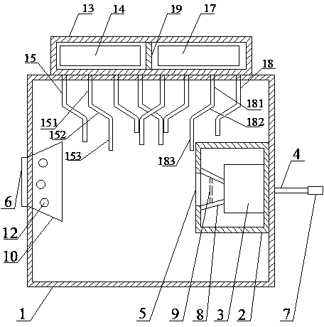
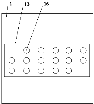
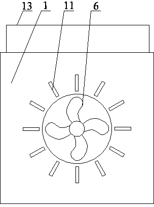
[0037] Such as Figure 1~Figure 3 As shown, the welder containing body includes a shell 1 with an open top, a box body 2, an air compressor 3, an air inlet pipe A4, an air outlet 5, and an exhaust fan 6. The box body 2 is fixed in the shell 1, and the air is compressed The machine 3 is fixed in the box body 2, the air inlet pipe A4 passes through the casing 1 and the box body 2 and is connected to the inlet of the air compressor 3, the air outlet 5 is arranged on the box body 2, and the air outlet 5 is facing the air compressor 3 Outlet, the exhaust fan 6 is arranged on the casing 1, and the exhaust fan 6 is facing the air outlet 5; it also includes a cover 13, a first fan 14 and a plurality of exhaust pipes 15, and the cover 13 is arranged on the top of the casing 1 , the first fan 14 is arranged in the cover body 13, the exhaust pipe 15 is arranged on the bottom of the cover body 13 and communicates with the inner space of the cover body 13, and the connection position betwe...


PUM


Abstract

The invention discloses a welding machine container. The welding machine container comprises a shell body with an open top, a box body, an air compressor, an air inlet pipe A, an air outlet and an exhaust fan, wherein the box body is fixed inside the shell body, the air compressor is fixed in the box body, the air inlet pipe A penetrates through the shell body and the box body to be connected with an inlet of the air compressor, the air outlet is formed in the shell boy, the air outlet right faces an outlet of the air compressor, and the exhaust fan is arranged on the shell body and right faces the air outlet. The welding machine container further comprises a cover body, a first fan and a plurality of air suction pipes, wherein the cover body is arranged at the top of the shell body, the first fan is arranged in the cover body, the air suction pipes are arranged at the bottom of the cover body and are communicated with the internal space of the cover body, the connection positions of the air suction pipes and the cover body are located in the range of the first fan, air holes are formed in the top of the cover body, and the lengths of the air suction pipes are different. The welding machine container has the advantages of being capable of achieving active heat dissipation, and good in heat dissipation effect.

Description

technical field [0001] The invention relates to the field of welding equipment, in particular to a welding machine containing body. Background technique [0002] The welding machine will generate high temperature and high heat during operation. If the generated heat cannot be dissipated in time, it will seriously affect the normal operation of the equipment, and even bring safety hazards. Therefore, it is imperative to dissipate heat from the welding machine. [0003] Existing welding machines realize the natural dissipation of heat therein by opening holes in the welding machine casing. However, this heat dissipation method is inefficient, and the heat generated by the welding machine cannot be dissipated at all when the welding machine is working at a high intensity. [0004] Now, there is an urgent need in the field for a device capable of actively dissipating heat to ensure the normal operation of the welding machine. Contents of the invention [0005] The purpose o...

Claims


Application Information

Patent Timeline
Patent Type & Authority Patents(China)
IPC IPC(8): B23K37/00
Inventor 王曾勇叶礼
Owner 沛县汉方机械制造股份有限公司
Learn More