Tool used for welding optical elements

An optical device and tooling technology, applied in the field of fixed tooling for welding, can solve the problems of low production efficiency, poor alignment accuracy, troublesome clamping process, etc., and achieve the effect of good stability and improved welding quality.

Inactive Publication Date: 2013-09-11
成都网动光电子技术股份有限公司
View PDF8 Cites 10 Cited by
  • Summary
  • Abstract
  • Description
  • Claims
  • Application Information

AI Technical Summary

Problems solved by technology

[0003] In order to solve the above-mentioned shortcomings in the welding of optical devices, the two parts to be welded have poor centering accur

Method used


Image

  • Tool used for welding optical elements

Examples


Embodiment 1

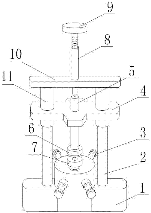
[0023] like figure 1 Shown: the tooling used for optical device welding of the present invention comprises a cylindrical lower object seat 7, a welding pedestal 1, and the middle part of the welding pedestal 1 is a hollow cylindrical structure, and the lower object seat 7 is placed in the hollow structure , also includes a plurality of adjusting bolts 3, the plurality of adjusting bolts 3 are evenly distributed on the same circumference of the hollow barrel structure, and are threadedly connected with the welding pedestal 1, the threaded end faces of the plurality of adjusting bolts 3 are connected to the lower The side of the object seat 7 is in contact, and the welding platform 1 is also provided with lugs symmetrical to the center line of the welding platform 1, and also includes two first vertical columns 2, a first beam 4, a pressure column 5, and a second vertical column 11 , the second beam 10 and the compression bolt 9, the first vertical column 2 is located in the ver...

Embodiment 2

[0026] This embodiment makes the following further limitations on the basis of embodiment 1: as figure 1 : the frock for optical device welding of the present invention includes welding pedestal 1, first vertical column 2, lower object seat 7, first beam 4, pressure column 5, second beam 10 and second vertical column 11, It also includes an upper object seat 6 and an inner wire sleeve 8. The welding platform 1, the first vertical column 2, the second vertical column 11, the lower object seat 7 and the upper object seat 6 are all made of cast iron that is not easy to rust and has low cost. The pressure column 5 and the first crossbeam 4 are made of stainless steel so as not to aggravate the wear of the mating surface of the pressure column 5 and the first beam 4 due to rust spots. Simultaneously, a section of the pressure column 5 close to the side of the upper end is also provided with concavo-convex patterns. The operator can conveniently hold the pressure column 5, which is ...


PUM


Abstract

The invention discloses a tool used for welding optical elements. The tool used for welding optical elements comprises a welding pedestal (1), a first vertical pillar (2), an adjustment bolt (3), a first cross beam (4), a pressing pillar (5), a discharging seat (7), a pressing bolt (9), a second cross beam (10) and a second vertical pillar (11). The tool used for welding optical elements is simple in structure, can act on optical elements to be welded through the pressing pillar or the combined action of the pressing pillar and the pressing bolt according to pressing requirements, and can effectively prevent relative displacement among the optical elements in the welding process. If the centering effect is not good after the optical elements are placed, the optical elements can be conveniently adjusted through the adjustment bolt. In addition, the optical elements are convenient to take and place, the selective pressing modes and the arranged adjustment bolt are both beneficial to the improvement of the welding efficiency.

Description

technical field [0001] The invention relates to a fixing tool for welding, in particular to a tool for welding an optical device. Background technique [0002] The optical device is the heart of the optical transmission system, and the welding quality between the various components of the optical device during the production process has a great influence on the performance of the optical device. Existing bench vises with cushions on the jaws are often used for optical device welding. The jaws hold a part of the optical device to be welded, and the other part to be welded is placed on it. This process requires the operator to ensure that the two parts are placed properly. The centering accuracy is high, but the upper part will be displaced with the lower part even under a weak external force, so that the welding quality cannot be guaranteed; and the installation and disassembly process of the optical device and the fixture is cumbersome, and the production efficiency is low. ...

Claims


Application Information

Patent Timeline
IPC IPC(8): B23K37/04
Inventor 黄兰
Owner 成都网动光电子技术股份有限公司
Why Eureka
Try Eureka