

Mold for injection molding, and manufacturing method for rubber product molded by using same
A technology of injection molding and mold, which is applied in the field of rubber product manufacturing, can solve problems such as inability to take out, lower productivity, rubber G1 residue, etc., and achieve the effect of suppressing residue and suppressing fracture
Inactive Publication Date: 2013-09-11
SUMITOMO RUBBER IND LTD
View PDF5 Cites 6 Cited by
- Summary
- Abstract
- Description
- Claims
- Application Information
AI Technical Summary
Problems solved by technology
[0004] However, in the case of the rubber product W, there is a problem that when the rubber product W is removed from the mold A, the exposed rubber g breaks at the root j of the sprue portion b1, and the rubber in the sprue portion b1 g1 remains on the mold side and cannot be taken out
In addition, the rubber g1 remaining in the sprue part b1 becomes a cause of a decrease in productivity, such as the inability to perform continuous automatic molding, so it must be removed.
Method used
View moreImage
Smart ImageViewing Examples

Examples
Embodiment
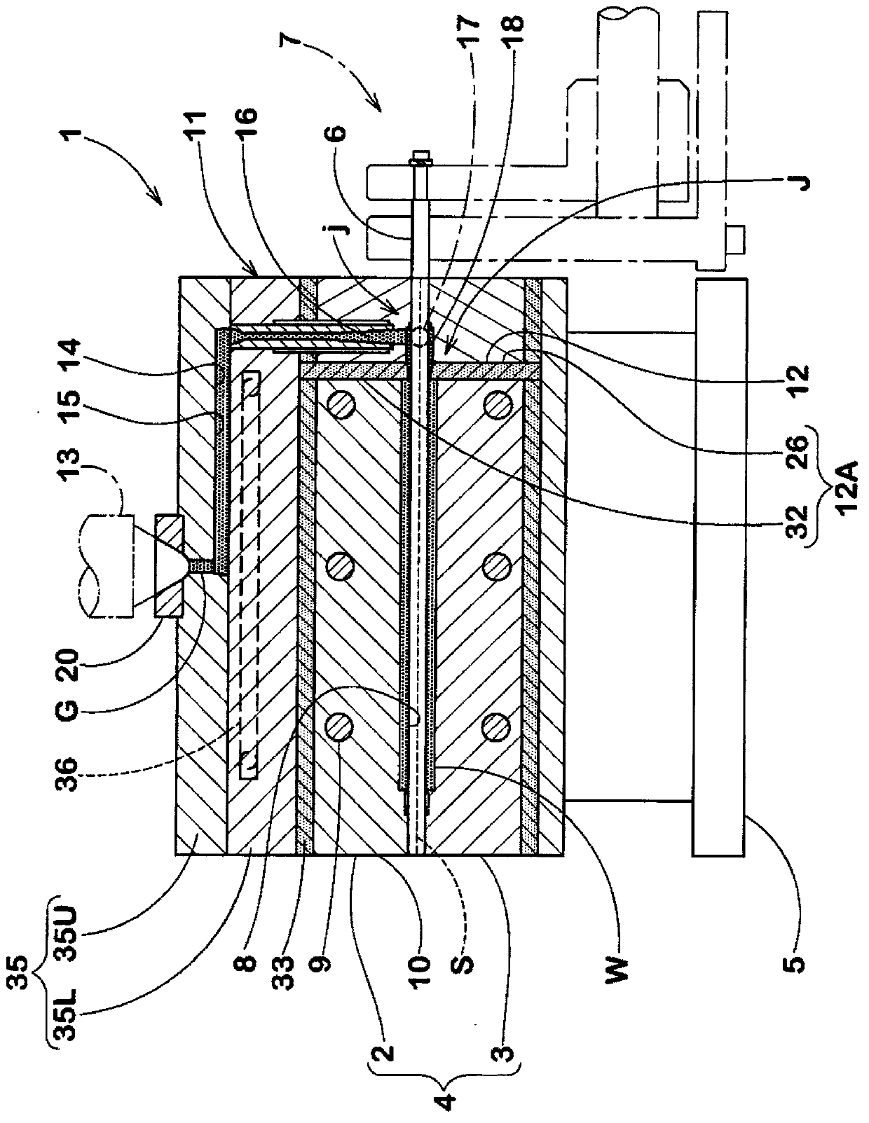
[0065] In order to confirm the effect of the present invention, according to the specifications of Table 1, a prototype was formed as figure 1 A mold for injection molding with the structure shown is shown, and 240 rubber rollers for copying machines were formed using this trial mold.
Login to View More PUM
| Property | Measurement | Unit |
|---|---|---|
| thermal conductivity | aaaaa | aaaaa |
| thermal conductivity | aaaaa | aaaaa |
Abstract
The present invention provides a mold for injection molding, and a manufacturing method for a rubber product molded by using the same. The mold can prevent rubber in a sprue portion from fracturing at the root of the rubber and residing in the sprue portion. A mold main body is divided into a product forming region and a rubber material feeding region, wherein the product forming region is provided with a mold cavity for forming the rubber product and a heater for heating and vulcanizing the rubber materials in the mold cavity; and the rubber material feeding region is provided with a rubber feeding flow path comprising a cooling runner portion, a sprue portion and a pouring gate portion. A thermal baffle plate is disposed between the product forming region and the rubber material feeding region. The thermal baffle plate inhibits the temperature of the rubber materials in the sprue portion, the runner portion and the pouring gate portion from increasing.
Description
technical field [0001] The present invention relates to a mold for injection molding that prevents the rubber in the sprue portion exposed from the rubber product from being broken at its root and remaining in the sprue portion (inside the mold) when the rubber product is removed from the mold, and a method using the mold Methods of manufacture of rubber products. Background technique [0002] E.g Figure 7 As shown in (A) and (B), in the injection mold A for injection molding the rubber product W, the rubber material is filled in the cavity c for forming the rubber product through the rubber supply flow path b, and the rubber material The supply channel b includes a cold runner (not shown), a sprue b1 , a runner b2 , and a gate b3 . Furthermore, the filled rubber material is heated and vulcanized in the cavity c, whereby the rubber product W is formed. [0003] Here, when the rubber product W is removed from the mold A, in order to make the rubber g in the sprue portion b...
Claims
Login to View More Application Information
Patent Timeline
 Patent Type & AuthorityApplications(China)
IPC IPC(8): B29C45/26B29C45/27B29C45/73B29C35/02B29C45/38B29K21/00
Inventor吉里成弘
OwnerSUMITOMO RUBBER IND LTD