Air conditioning system for motor vehicles

A technology for an air conditioning system and a motor vehicle, which is applied in the field of air conditioning systems for motor vehicles, can solve problems such as poor comfort in the cabin, and achieve the effect of preventing discomfort

Active Publication Date: 2013-09-11
HANON SYST
View PDF5 Cites 5 Cited by
  • Summary
  • Abstract
  • Description
  • Claims
  • Application Information

AI Technical Summary

Problems solved by technology

This leads to an even worse problem with cabin comfort

Method used


Image

  • Air conditioning system for motor vehicles
  • Air conditioning system for motor vehicles
  • Air conditioning system for motor vehicles

Examples


no. 1 approach

[0036] Before describing the features of the air conditioning system for a motor vehicle according to the invention, reference will be made to Figure 4 Briefly describe the general configuration of an air conditioning system.

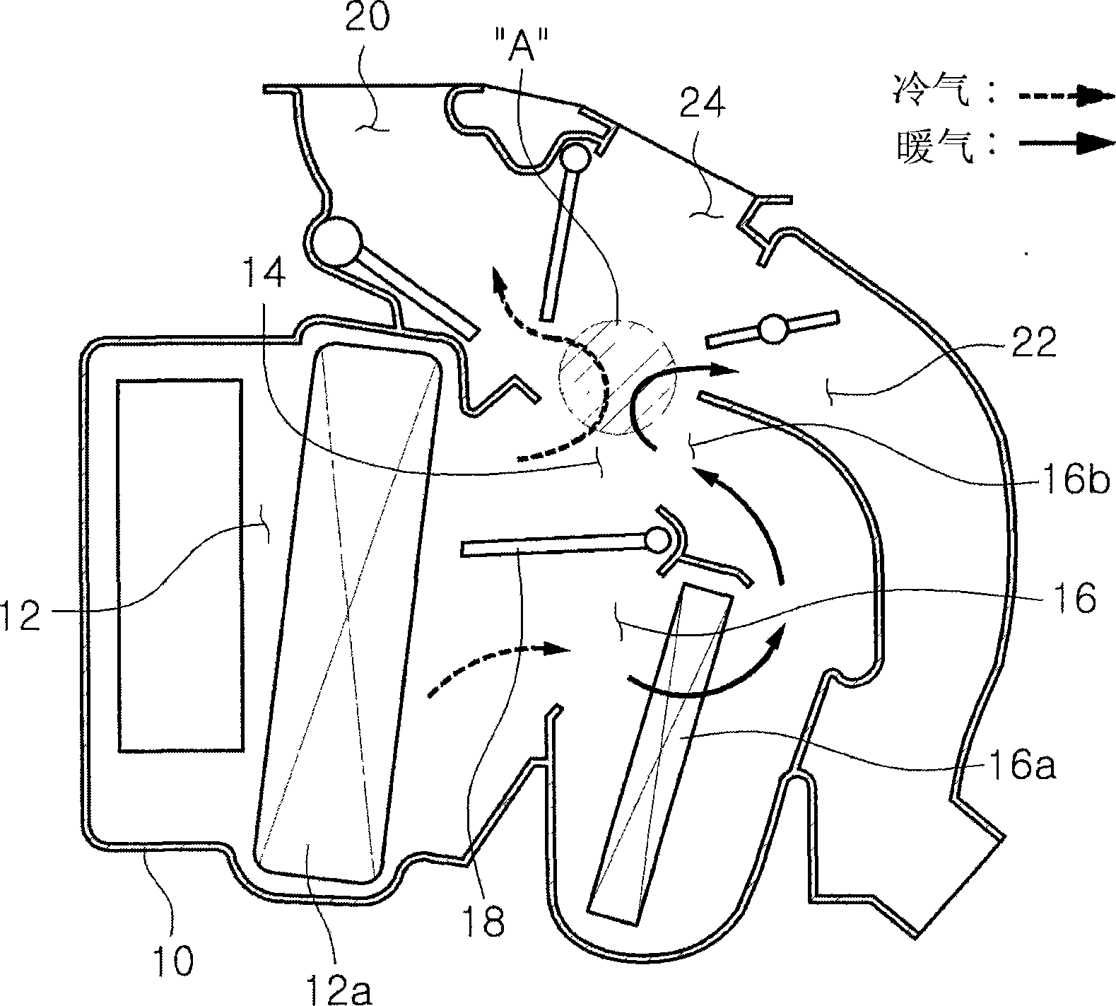
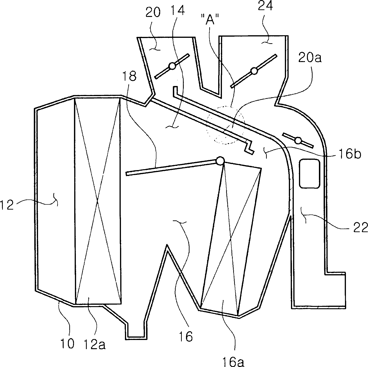
[0037] A current air conditioning system includes an air conditioning housing 10 in which a main flow channel 12 is formed. The evaporator 12 a is installed in the main flow channel 12 . The evaporator 12 a serves to cool the air flowing along the main flow channel 12 .

[0038] The main channel 12 is bifurcated into a cold air channel 14 and a warm air channel 16 . The heater core 16 a is installed in the heating duct 16 . The temperature control door 18 is arranged at the bifurcation point of the cold air passage 14 and the warm air passage 16 . Cool air cooled by the evaporator 12 a passes through the cool air passage 14 . The warm air heated by the heater core 16 a passes through the warm air duct 16 .

[0039] The temperature control door 18...

no. 2 approach

[0062] Figure 9 An air conditioning system according to a second embodiment of the present invention is shown. The air conditioning system of the second embodiment includes a cool air introduction cutout portion 50 formed in the outlet 36 of the bypass duct 30 . The cool air introduction cutout portion 50 is formed by partially cutting the outlet 36 of the bypass duct 30 and is arranged in an opposing relationship to the cool air passage 14 . In the present embodiment, the cool air introducing cutout portion 50 is used as the cool air introducing means.

[0063] A part of the cool air flowing through the cool air passage 14 is introduced into the bypass duct 30 through the cool air introduction cutout portion 50 . The cold air thus introduced is mixed with the split warm air flowing through the bypass duct 30 , thereby lowering the temperature of the split warm air flowing through the bypass duct 30 . As a result, the temperature of warm air flowing to the defrosting vent ...


PUM


Abstract

An air conditioning system for motor vehicles includes an air conditioner case, a cold air path through which a cold air flows, a warm air path through which a warm air flows, a temperature control door arranged to swing between the cold air path and the warm air path so as to control an opening degree of the cold air path and an opening degree of the warm air path, a defrost vent arranged to discharge the cold air and the warm air toward an upper region of a vehicle room, a bypass duct arranged to bypass a part of the warm air toward the defrost vent, the bypass duct including an inlet aligned with the warm air path and an outlet aligned with the defrost vent, and a cold air introducing portion arranged in at least one of the inlet and the outlet of the bypass duct.

Description

technical field [0001] The present invention relates to an air-conditioning system for a motor vehicle, and more particularly, to such an air-conditioning system for a motor vehicle in which the warm air flowing through the heating duct is diverted towards the defrost vent so as to increase the temperature of the upper area of ​​the passenger compartment. During the temperature period, cold air allowed to flow through the cool air passage can partially enter the cabin, thereby preventing the phenomenon that the temperature of the upper area of ​​the cabin rises too high, and also prevents the phenomenon that the cabin environment becomes uncomfortable. Background technique [0002] Motor vehicles are provided with air conditioning systems for cooling or heating the cabin. as attached figure 1 As shown, the air-conditioning system includes an air-conditioning casing 10 in which a main flow channel 12 is formed. Indoor air or outdoor air blown from a blower (not shown) flows...

Claims


Application Information

Patent Timeline
Patent Type & Authority Applications(China)
IPC IPC(8): B60H1/00
CPCB60H2001/00092B60H2001/00164B60H1/00064B60H2001/00721B60H1/00678B60H1/247B60J1/002
Inventor 金斗勋韩仲万李俊康朴祥奎韩永钦南遂炳
Owner HANON SYST
Why Eureka
Try Eureka