Supercharge Your Innovation With Domain-Expert AI Agents!

Material plate distribution device of cartoning machine and its cartoning machine

A technology of cartoning machine and material board, which is applied in the direction of packaging, etc., can solve the problems of overlapping structure of swing rod parts, easy throwing on the partition, feeding failure and other problems, so as to improve stability and reliability, expand the scope of application, Change the effect of unloading misalignment

Active Publication Date: 2016-03-23
江西创一精密机械有限公司
View PDF6 Cites 0 Cited by
  • Summary
  • Abstract
  • Description
  • Claims
  • Application Information

AI Technical Summary

Problems solved by technology

[0002] In the material sheet distribution device of the existing cartoning machine, each suction cup must be equipped with a corresponding stretching and swinging mechanism, which makes the structure of the stretching and swinging mechanism extremely complicated. Large, because the swing or rotation direction of the swing mechanism of this structure can only be the same as or parallel to the conveying direction of the feed conveyor belt, it is difficult to accurately place the material plate in the corresponding position due to the swing inertia during the swing operation during suction and discharge In the partition (collection room), it is easy to throw on the partition and cause feeding failure; in addition, the material board in the silo of the distribution device of this type of structure must be tangent to the movement track of the extension and swing mechanism, and the hopper can only It is located directly above the partition (conveyor belt), and the movement track of the material plate will touch the partition, and when the material bin falls off, it will directly fall onto the conveyor belt and cause a box feeding failure

Method used


Image

  • Material plate distribution device of cartoning machine and its cartoning machine
  • Material plate distribution device of cartoning machine and its cartoning machine
  • Material plate distribution device of cartoning machine and its cartoning machine

Examples


Embodiment Construction

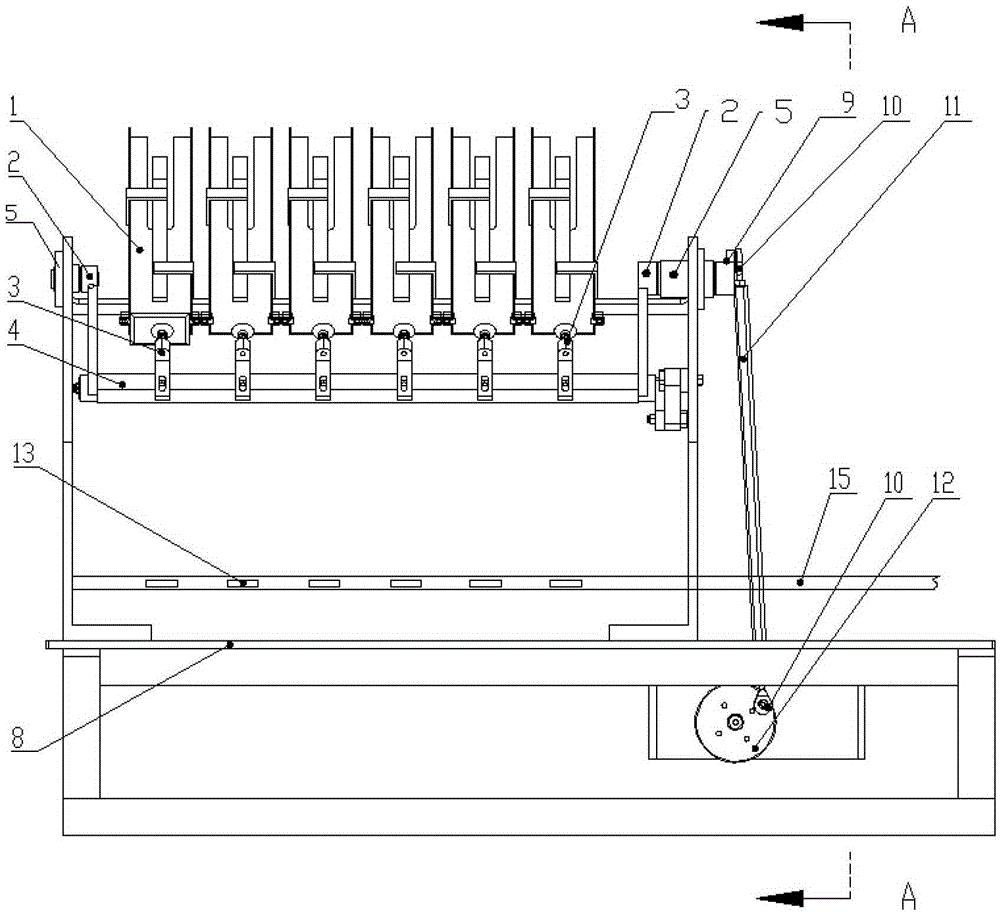
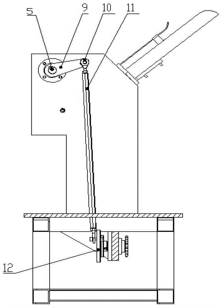
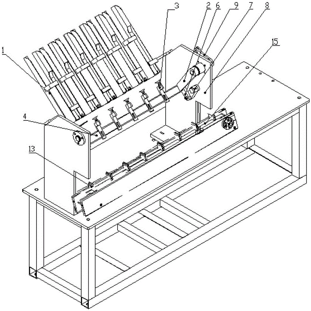
[0014] The present invention will be described further by embodiment now in conjunction with accompanying drawing. The hopper of the material plate distribution device of the present invention can be located at any position in the conveying direction of the conveyor belt on the upper part of the collecting chamber, that is, it can be installed directly above the conveyor belt (synchronous conveyor belt) or on the conveyor belt. Above one side of the belt; the axial direction of the movable pendulum shaft of the material sheet distribution device can be the same as the conveying direction of the conveyor belt, or the two form an angle less than 10 degrees with each other, and the suction cup assembly of the material sheet distribution device ( Suction cup) rotates or swings along the transverse direction of the conveyor belt, or rotates or swings around the conveying direction line of the conveyor belt.

[0015] The present embodiment of material plate distributing device is fo...


PUM


Abstract

The invention discloses a material plate delivery device of a boxing machine and the boxing machine comprising the material plate delivery device, wherein the material plate delivery device and the boxing machine comprising the material plate delivery device are accurate and reliable in delivery, high in material plate delivery and boxing speed, simple in structure and good in universality. The material plate delivery device comprises a conveying belt, one or more collection chambers arranged on the conveying belt, one or more corresponding stock bins corresponding to the collection chambers, one or more sucking disks corresponding to the collection chambers and the corresponding stock bins, and a movable swing shaft, wherein the axial direction of the movable swing shaft corresponds to the conveying direction of the conveying belt, and the movable swing shaft is connected to a rack through a corresponding swing mechanism. The sucking disks are connected to the movable swing shaft. The boxing machine comprises the material plate delivery device, and the material plate delivery device is the material plate delivery device shown in the right claim 1 or 2.

Description

technical field [0001] The invention relates to a cartoning machine, in particular to a material sheet distribution device of the cartoning machine and the cartoning machine thereof. Background technique [0002] In the material sheet distribution device of the existing cartoning machine, each suction cup must be equipped with a corresponding stretching and swinging mechanism, which makes the structure of the stretching and swinging mechanism extremely complicated. Large, because the swing or rotation direction of the swing mechanism of this structure can only be the same as or parallel to the conveying direction of the feed conveyor belt, it is difficult to accurately place the material plate in the corresponding position due to the swing inertia during the swing operation during suction and discharge In the partition (collection room), it is easy to throw on the partition and cause feeding failure; in addition, the material board in the silo of the distribution device of t...

Claims


Application Information

Patent Timeline
Patent Type & Authority Patents(China)
IPC IPC(8): B65B35/38B65B35/44
Inventor 龙良德李国兴冯包明蒋志坚王景山
Owner 江西创一精密机械有限公司
Features
  • R&D
  • Intellectual Property
  • Life Sciences
  • Materials
  • Tech Scout
  • Unparalleled Data Quality
  • Higher Quality Content
  • 60% Fewer Hallucinations
Learn More