Suction device of washing machine and washing machine

A washing machine and feeder technology, applied in the field of washing machines, can solve the problems of large power consumption, large water consumption, long time consumption, etc., and achieve the effects of avoiding waste, improving washing efficiency, and smooth particle conveying

Active Publication Date: 2013-09-11
QINGDAO HAIER MOLDS
View PDF3 Cites 4 Cited by
  • Summary
  • Abstract
  • Description
  • Claims
  • Application Information

AI Technical Summary

Problems solved by technology

This method simply drains the water and refills it with clean wash water, which consumes a lot of water
At the same time, the washing liquid also contains more chemical substances harmful to the environment, and each washing process takes a long time and consumes a lot of power.

Method used


Image

  • Suction device of washing machine and washing machine
  • Suction device of washing machine and washing machine
  • Suction device of washing machine and washing machine

Examples


Embodiment 1

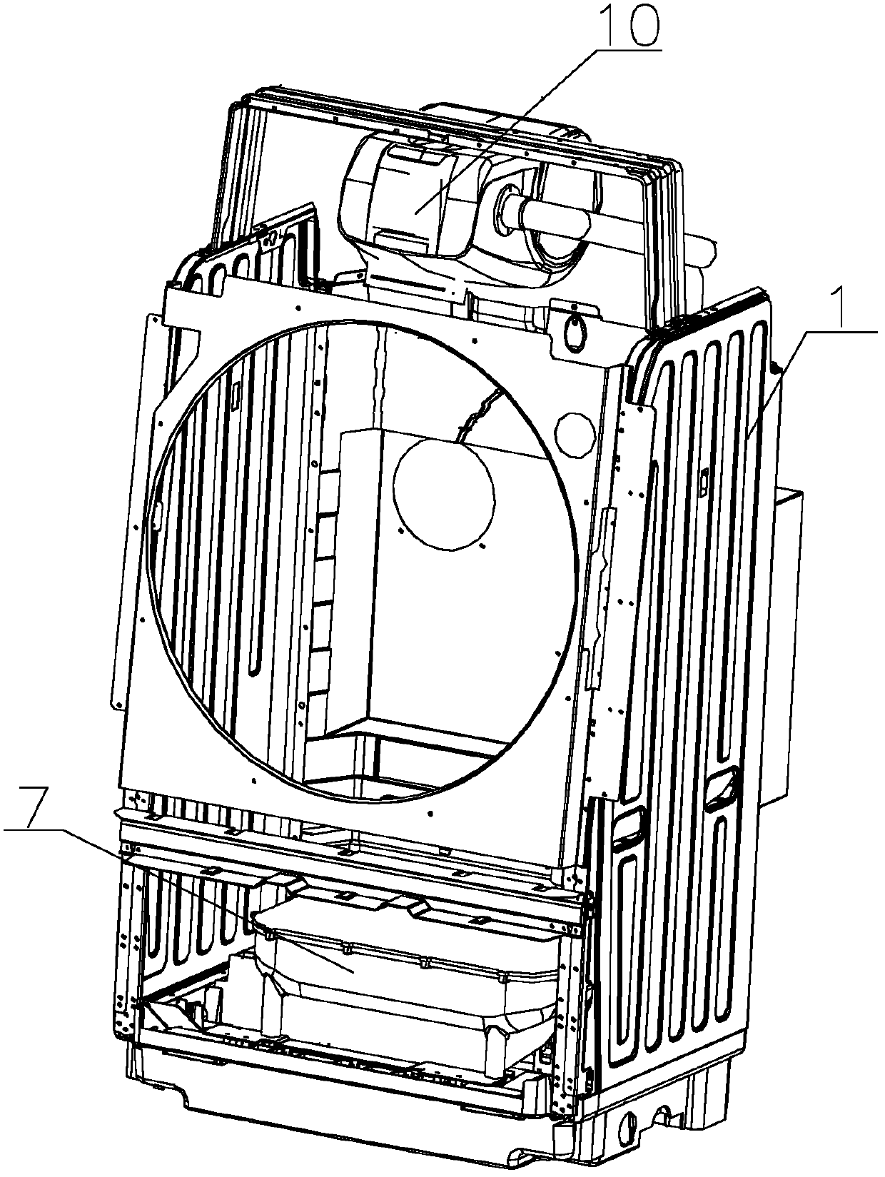
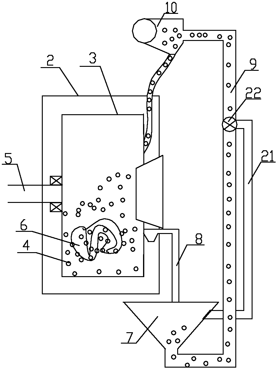
[0027] Such as figure 1 and figure 2 As shown, a washing machine is described in detail in this embodiment with a drum washing machine as an example. The washing machine includes a housing 1, and an outer cylinder 2, an inner cylinder 3 and solid particles 4 as a washing medium are arranged in the housing 1, wherein , the outer cylinder 2 is fixed and non-rotating, and is mainly used for holding water. The inner cylinder 3 is used for washing. The inner cylinder 3 is arranged on the inner side of the outer cylinder 2. The inner cylinder 3 is driven to rotate by the driving device 5, and the clothes 6 and particles 4 are placed in the In the inner cylinder 3, several water permeable holes for washing water to pass are evenly opened on the wall of the inner cylinder 3. The diameter of the water permeable holes is smaller than the diameter of the solid particles 4. The shape of the water permeable holes can be circular, rectangular, Polygon etc. A water inlet (not shown) is pr...

Embodiment 2

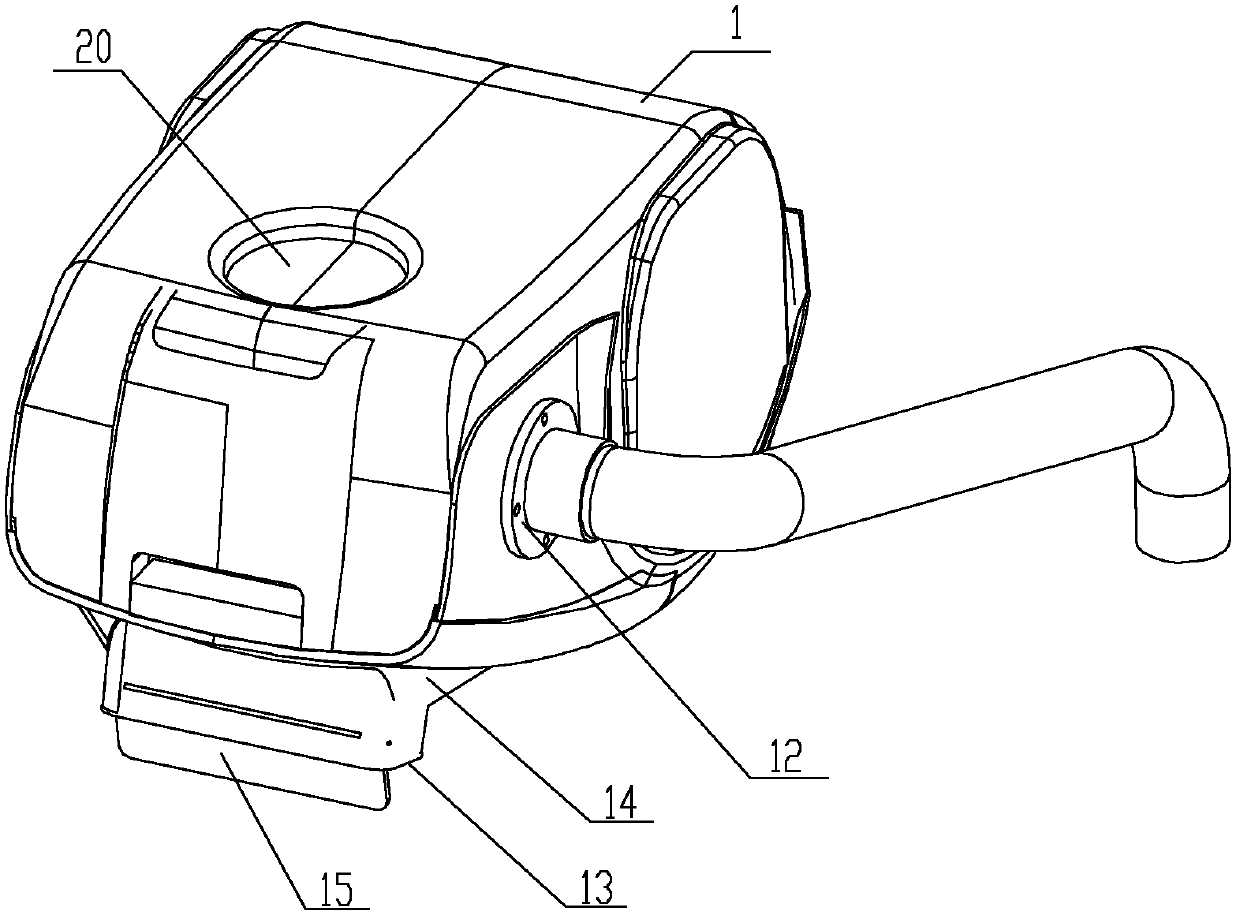
[0049] The difference from Embodiment 1 is that the baffle plate 15 at the discharge port 13 of the suction device 10 is connected with a motor for driving the baffle plate 15 to rotate, and the motor 15 is connected with the controller of the washing machine, and the controller of the washing machine controls the fan. The number of times and time of opening and the opening and closing of the valve control the quantity in the inner cylinder 3.

Embodiment 3

[0051] The difference from Embodiment 1 is that a valve is arranged at the discharge port 13 of the material suction device 10, the valve is connected with the controller of the washing machine, and the number of times and the time of fan opening and the opening and closing of the valve are controlled by the controller of the washing machine, and then Control the quantity that drops in inner tube 3.


PUM


Abstract

The invention relates to a suction device of a washing machine and the washing machine. The washing machine comprises an inner barrel, an outer barrel, washing particles serving as the washing media, and a storage tank used for storing the particles. The suction device is further arranged in the washing machine and comprises a casing and a fan, wherein a feed inlet, a discharge outlet and an exhaust port are formed in the casing; the exhaust port is formed in the air inlet end or air outlet end of the fan; a discharge funnel is arranged at the bottom of the casing; the discharge outlet is formed in the bottom of the discharge funnel; and a baffle or a control valve used for opening or closing the discharge outlet is arranged at the discharge outlet. According to the suction device and the washing machine, the particles in the storage tank are sucked out by the fan automatically, stored temporarily in the suction device, and thrown into the outer barrel or the inner barrel, so that the particles are delivered more smoothly; meanwhile, during particle separation and recovery, suction out of the particles and delivery into the storage tank are also facilitated; the baffle structure is used to achieve quantitative particle throwing, not only can the washing efficiency be improved, but also waste can be avoided.

Description

technical field [0001] The invention relates to a washing machine, in particular to a washing machine suction device arranged in the washing machine for particle flow and storage and a washing machine using the suction box, belonging to the technical field of washing machines. Background technique [0002] The washing method of the traditional washing machine is to use water as the washing medium, add water and detergent to the washing machine for washing, use the dehydration function to discharge the sewage in the washing machine after washing, and then re-add clean water to continue the washing or rinsing process. Drain the water after all the washing is finished. This method simply drains the water and refills it with clean washing water, which consumes a lot of water. At the same time, the washing liquid also contains more chemical substances harmful to the environment, and each washing process takes a long time and consumes a lot of power. [0003] Aiming at the short...

Claims


Application Information

Patent Timeline
Patent Type & Authority Applications(China)
IPC IPC(8): D06F35/00
Inventor 耿斌齐弘韬钟诚何政保王晓燕王虎
Owner QINGDAO HAIER MOLDS
Why Eureka
Try Eureka