A circulation pump sealing structure under negative pressure/normal pressure state

A sealed structure, circulating pump technology, applied in the parts, pumps, pump elements, etc. of the pumping device for elastic fluid, can solve the problem of difficult suction and pumping, reduced performance and service life, pump function failure, etc. problems, to achieve the effect of extending the service life, ensuring continuous use, and avoiding dry friction

Inactive Publication Date: 2016-02-10
涂晶 +1
View PDF6 Cites 0 Cited by
  • Summary
  • Abstract
  • Description
  • Claims
  • Application Information

AI Technical Summary

Problems solved by technology

[0002] All kinds of circulating pumps commonly used in the market are not suitable for pumping liquids under negative pressure, especially when the pressure is lower than 50KPa, it is more difficult to complete the function of suction and pumping
Therefore, when the atmospheric pressure is higher than the pressure in the pump, the air is poured into the pump through the sealing ring, causing the sealing ring to be unable to seal and lubricate, resulting in dry friction of the sealing ring, so that a large amount of air squeezes the liquid in the pump through the sealing ring. Space causes the pump to fail, reducing pump performance and service life

Method used


Image

  • A circulation pump sealing structure under negative pressure/normal pressure state

Examples


Embodiment Construction

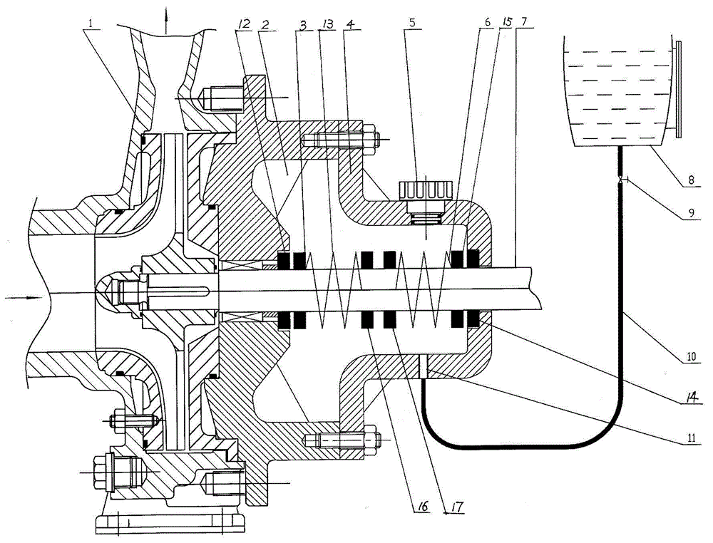
[0008] A circulation pump sealing structure under negative pressure / normal pressure, such as figure 1 As shown, a spring seat is fixed on the transmission shaft 7 in the sealed chamber 2 of the circulating pump 1, and the spring seat pushes the first moving ring 3 with the sealing ring through the first spring 13 to communicate with the first stationary ring 12 with the sealing ring. Cooperate, the transmission shaft 7 on the other side of the spring seat is provided with a spring seat to push the second moving ring 15 with a sealing ring through the second spring 6 to cooperate with the second static ring 14 with a sealing ring, and the second static ring 14 The sealing ring matches the concave platform on the shaft hole of the pump cover 4 in the sealing chamber. The pump cover 4 is a barrel-shaped gland with a connecting flange, and an oil inlet hole 11 is arranged on the lower part of the barrel surface of the pump cover 4. The oil outlet at the bottom of the high-level oi...


PUM


Abstract

The invention discloses a circulating pump sealing structure under a negative / atmospheric pressure state, which is characterized in that a transmission shaft in a sealing cavity of a circulating pump is fixedly connected with a spring seat; the spring seat pushes a first moving ring with a sealing ring to be matched with a first stationary ring with a sealing ring through a first spring; another spring seat is arranged on the transmission shaft on the other side of the spring seat and pushes a second moving ring with a sealing ring to be matched with a second stationary ring with a sealing ring through a second spring; the sealing ring of the second stationary ring is matched with a concave platform on a shaft hole of a sealing cavity pump cover; the pump cover is a bucket-shaped gland with a connecting flange; an oil inlet is formed at the lower part of a bucket surface of the pump cover; an oil outlet at the bottom of a high oil tank above the circulating pump is connected with an oil pipe; the lower end of the oil pipe is connected with the oil inlet of the pump cover; and a vent valve is arranged at the upper part of the bucket surface of the pump cover. According to the structure, when the circulating pump sucks liquid under the negative pressure state, the circulating pump can operate continuously and stably, the dry friction of the sealing rings is avoided, the continuous utilization function of the circulating pump is ensured, and the service life of the circulating pump is prolonged.

Description

technical field [0001] The invention belongs to the improvement of the sealing structure of a circulating pump, in particular to a sealing structure of a circulating pump under negative pressure / normal pressure. Background technique [0002] Various circulation pumps commonly used in the market are not suitable for pumping liquids under negative pressure, especially when the pressure is lower than 50KPa, it is more difficult to complete the functions of suction and pumping. Therefore, when the atmospheric pressure is higher than the pressure in the pump, the air is poured into the pump through the sealing ring, causing the sealing ring to be unable to seal and lubricate, resulting in dry friction of the sealing ring, so that a large amount of air squeezes the liquid in the pump through the sealing ring. Space causes the pump to fail, which in turn reduces pump performance and service life. Contents of the invention [0003] The object of the present invention is to provid...

Claims


Application Information

Patent Timeline
Patent Type & Authority Patents(China)
IPC IPC(8): F04D29/12
Inventor 涂晶涂莹
Owner 涂晶
Why Eureka
Try Eureka