
Motor-driven plug-in mounting flow servo valve

A motor-driven, servo valve technology, applied in the hydraulic field, can solve the problems of high price, complicated control system, troublesome debugging and maintenance, etc., and achieve the effect of simplifying structure, reducing cost and simple price

Active Publication Date: 2013-09-11
AEMETEC
View PDF8 Cites 4 Cited by
  • Summary
  • Abstract
  • Description
  • Claims
  • Application Information

AI Technical Summary

Problems solved by technology

This kind of cartridge flow servo valve has a complex structure, and it is necessary to install two position sensors on the cone valve core and the servo valve core to realize multi-closed-loop control. The system is complex, debugging and maintenance are more troublesome, and the price is also expensive

Method used


Image

  • Motor-driven plug-in mounting flow servo valve
  • Motor-driven plug-in mounting flow servo valve
  • Motor-driven plug-in mounting flow servo valve

Examples


Embodiment Construction

[0034] In order to make the object, technical solution and advantages of the present invention clearer, the present invention will be further described in detail below in conjunction with the accompanying drawings and embodiments. It should be understood that the specific embodiments described here are only used to explain the present invention, not to limit the present invention.

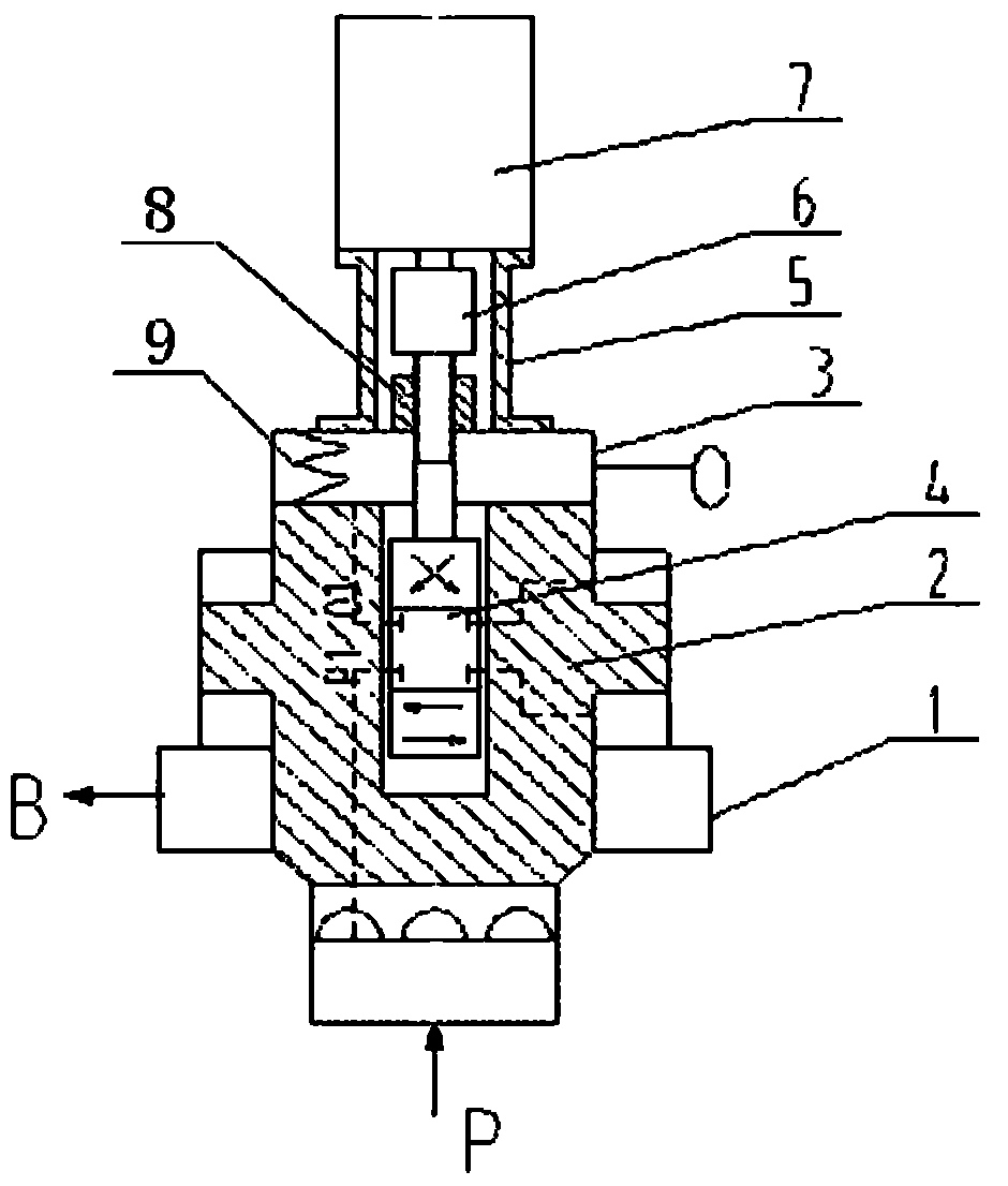
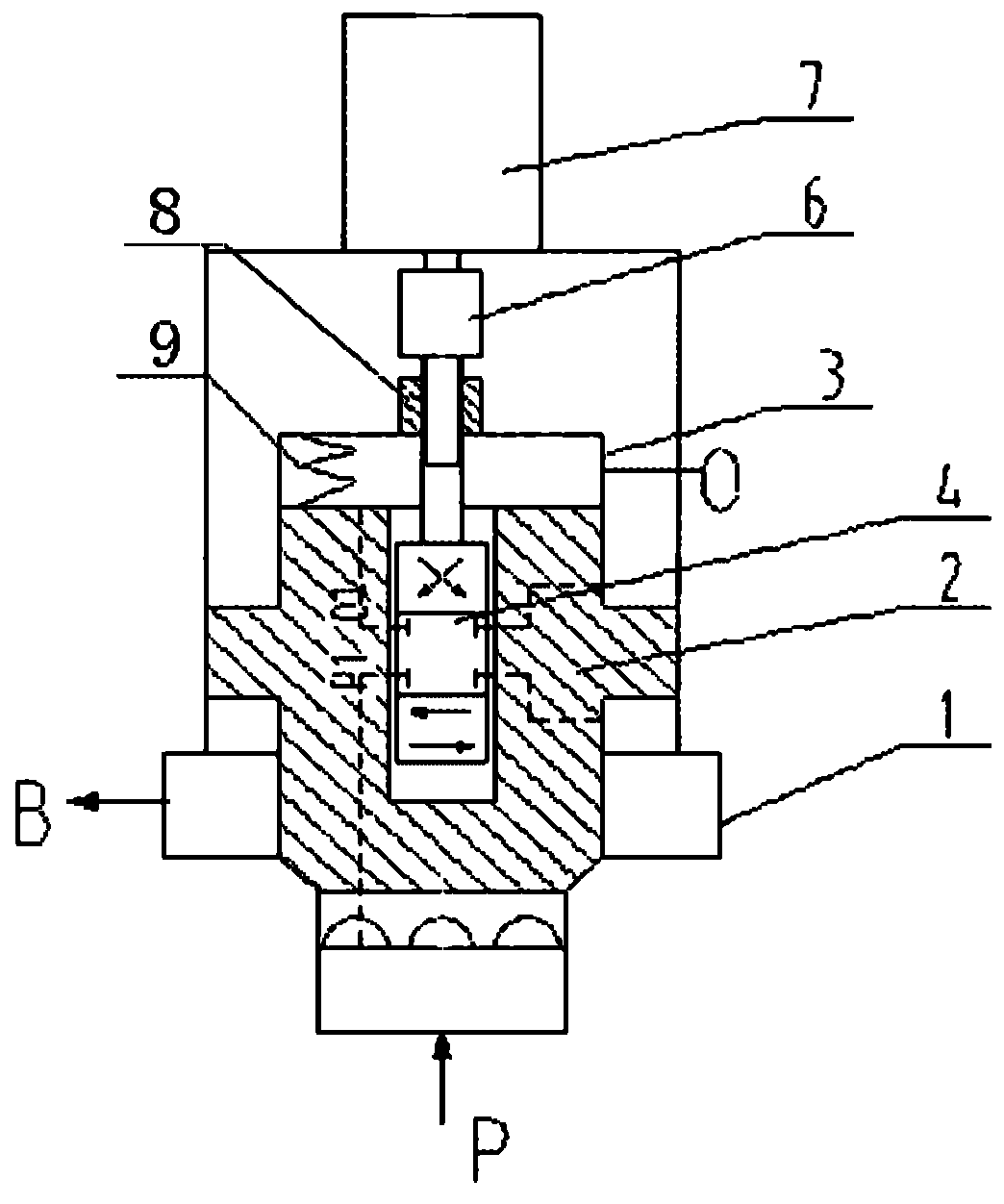
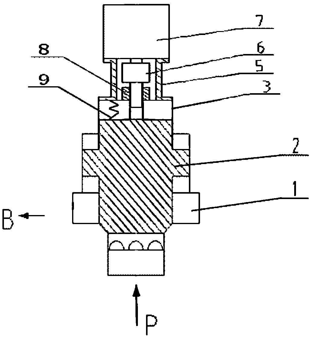
[0035] Please refer to figure 1 , in one embodiment of the present invention, the motor-driven plug-in flow servo valve includes a valve body 1, a cone spool 2, a gland 3 with a fluid return port O, a control spool 4, and a motor support 5 , Connecting device, that is, sliding coupling 6, motor 7, nut 8, spring 9. There are fluid inlet P, fluid outlet B and corresponding holes on the valve body 1. There are steps on the control spool 4 and are installed in the inner cavity of the cone spool 2. There are holes P1 and O1 on the cone spool 2. The control valve The step of the core 4 matches the hole...


PUM


Abstract

The invention provides a motor-driven plug-in mounting flow servo valve which is applicable to the hydraulic field, and comprises a valve body, a cone valve element, a control valve element, a gland, a spring, a motor, a nut and a connecting device, wherein a fluid inlet and a fluid outlet are formed in the valve body; a step is arranged on the control valve element; aperture passages are formed in the cone valve element; a fluid reflux inlet is formed in the gland; the nut is fixedly connected with the gland; a thread is formed at one end of the control valve element; and one end of the thread passes through the gland and is meshed with the nut, and is connected with a motor output end through the connecting device. The motor-driven plug-in mounting flow servo valve has a simple structure, and the flow of a single-stage valve can be high. Through the addition of flow detection and the position detection and uninterrupted control to the corner and the direction of the motor, the functions of a proportioning valve and a servovalve can be finished, so that the purpose that one valve is multi-purpose is achieved. The invention further provides another motor-driven plug-in mounting flow servo valve which adopts the motor to directly drive the cone valve element, and is full-electric.

Description

technical field [0001] The invention relates to the hydraulic field, in particular to a motor-driven cartridge flow servo valve. Background technique [0002] In fluid transmission, the cartridge flow servo valve has the advantages of simple structure and large flow rate, so it is widely used in hydraulic systems, especially the hydraulic control of heavy-duty main engines, and the cartridge flow servo valve is inseparable. The traditional cartridge flow servo valve includes a servo valve and a servo cylinder. The piston rod of the servo cylinder is made into a cone valve core, and the displacement of the cone valve core is controlled to control the opening of the cone valve, thereby controlling the output flow. This kind of cartridge flow servo valve has a complex structure, and it is necessary to install two position sensors on the cone valve core and the servo valve core to realize multi-closed-loop control. The system is complex, debugging and maintenance are more troub...

Claims


Application Information

Patent Timeline
Patent Type & Authority Applications(China)
IPC IPC(8): F15B13/02
Inventor 杨世祥杨涛杨帆李桂英
Owner AEMETEC
Learn More