
Lifting mechanism

A lifting mechanism and lifting rod technology, which is applied in the direction of supporting machines, mechanical equipment, machine platforms/supports, etc., can solve the problems of inability to solve flexible detection, no lifting mechanism, etc., to achieve flexible movements, stable and reliable lifting and recovery , small size effect

Active Publication Date: 2015-07-15
CITIC HIC KAICHENG INTELLIGENT EQUIP CO LTD
View PDF7 Cites 0 Cited by
  • Summary
  • Abstract
  • Description
  • Claims
  • Application Information

AI Technical Summary

Problems solved by technology

Although this technical solution has superior explosion-proof performance and good ground adaptability, it does not provide a suitable lifting mechanism, so it cannot solve the problem of flexible detection

Method used


Image

  • Lifting mechanism
  • Lifting mechanism
  • Lifting mechanism

Examples


Embodiment Construction

[0038] The technical solutions of the present invention will be described in detail below in conjunction with the accompanying drawings and specific embodiments.

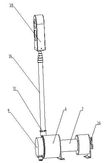
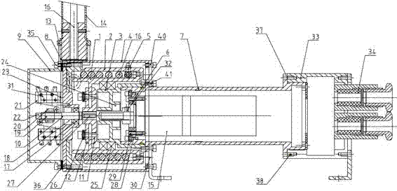
[0039] In a preferred embodiment of the present invention, a novel lifting mechanism with small volume and flexible movements is provided. attached figure 1 describes this lifting mechanism as figure 1 As shown, the lifting mechanism includes a head, a main cavity, and a tail. Specifically, the head part is a wiring cavity, the main cavity is composed of a lifting rod and a casing cavity, and the casing cavity includes a flameproof cavity, and the tail part is composed of a control panel cavity.

[0040] The head part and the main cavity are fastened and connected by a fastening device 35, and the connection methods include but are not limited to bolts, pins, screws and the like. Preferably, the fastening device 35 is a hexagon socket head cap screw 35 . More preferably, the connection between the head part and ...


PUM


Abstract

The invention provides a lifting mechanism which comprises a head portion, a main cavity body and a tail portion, wherein the head portion is a wiring cavity, the main cavity body is composed of a lifting rod (14) and an outer shell cavity (4), the lifting rod (14) is connected with the outer shell cavity (4) through a threaded structure, the tail portion is a control panel cavity, the head portion and the main cavity body are firmly connected through a fastening device (35), and the main cavity body and the tail portion are firmly connected through a fastening device (37). The inner structure of the wiring cavity (9) of the head portion comprises a rotating shaft (10) and a limiting installation block (19), a threaded hole of the limiting installation block (19) is screwed into the transmission shaft (10), and the lifting rod (14) is fixedly connected with the explosive-proof cavity (4) through a locking nut (13). The lifting mechanism has the advantages of being flexible in motion, small in size, stable and reliable in rising and recovery of the lifting rod, free of influencing the passing ability of an underground detection robot or other equipment, and capable of meeting actual detection needs by means of adjustment of the number of grades of the lifting rod due to the fact that the lifting rod is of a multi-grade structure. Moreover, a top end device of the lifting rod can determine the type of equipment needing to be lifted according to using requirements.

Description

technical field [0001] The invention relates to a liftable mechanical structure for mining, in particular to a lifting mechanism for a mining detection robot, which belongs to auxiliary equipment for a mining detection robot. Background technique [0002] In the process of coal production, due to the complex environment in coal mines, some unforeseen disasters or accidents often occur, such as water seepage, roof fall, gas explosion, coal dust explosion, etc. Once an accident occurs, the life safety of the miners will be greatly threatened, and it will bring huge losses to the country and the people. After a mining accident, there is a large amount of toxic gas underground, and it is particularly important for mining detection robots to detect the accident site. [0003] However, in the prior art, the detection height of the detection robot is limited, and it cannot detect the toxic gas at a high place. [0004] For example, the patent document with the patent number ZL200...

Claims


Application Information

Patent Timeline
Patent Type & Authority Patents(China)
IPC IPC(8): F16M11/28F16M11/42E21F17/00
Inventor 许开成陆文涛张树生刘小林
Owner CITIC HIC KAICHENG INTELLIGENT EQUIP CO LTD
Features
  • Generate Ideas
  • Intellectual Property
  • Life Sciences
  • Materials
  • Tech Scout
  • Unparalleled Data Quality
  • Higher Quality Content
  • 60% Fewer Hallucinations
Learn More