Air conditioning system

An air conditioning system and air conditioner technology, which is applied in the heating system, high-efficiency regulation technology, heating and ventilation control system, etc., can solve the problems of not being refrigerated, not considering the heating of the motor and controlling the heating of the substrate, so as not to damage the comfort Effect

Active Publication Date: 2013-09-11
MITSUBISHI ELECTRIC CORP
View PDF7 Cites 10 Cited by
  • Summary
  • Abstract
  • Description
  • Claims
  • Application Information

AI Technical Summary

Problems solved by technology

[0006] In the conventional air conditioners provided with auxiliary cooling operation by introduction of outside air as in Patent Documents 1 and 2, the difference between the outside air temperature and the indoor temperature or the difference between the outside air temperature and the indoor set temperature is used to The judgment of the introduction of external air does not take into account losses such as the heat generated by the motor and the heat generated by the control board when the external air is introduced
Therefore, even if the outside air is introduced into the room, there is a problem that it is not actually cooled.

Method used


Image

  • Air conditioning system
  • Air conditioning system
  • Air conditioning system

Examples


Embodiment approach 1

[0017] Below, based on figure 1 , figure 2 Embodiment 1 will be described.

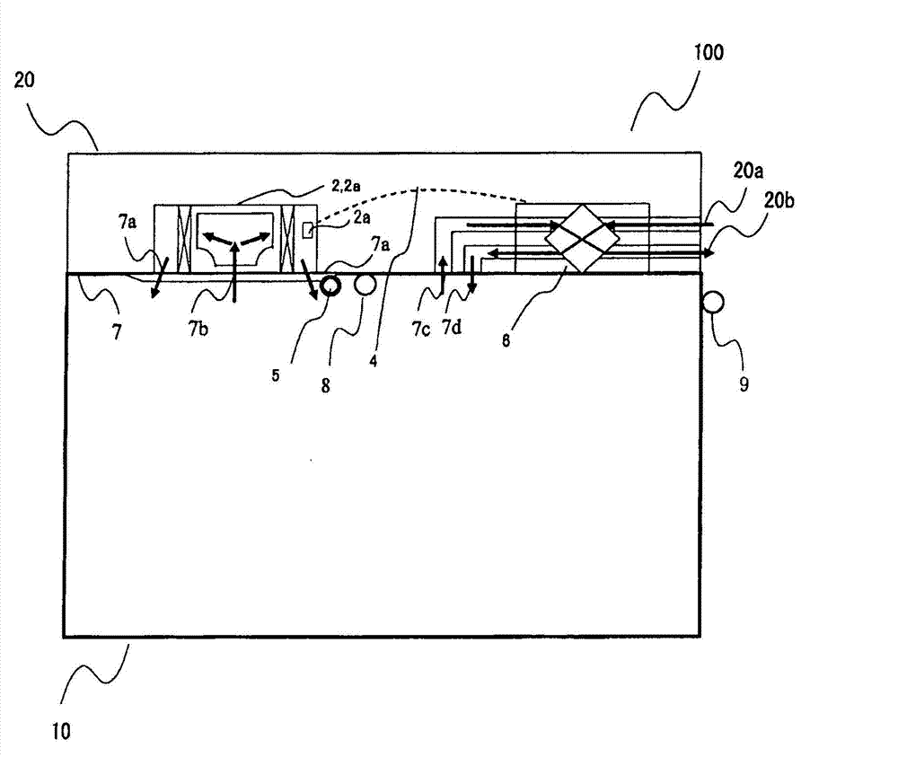
[0018] figure 1 It is a figure which shows the structure of the air conditioning system 100 which concerns on Embodiment 1 of this invention.

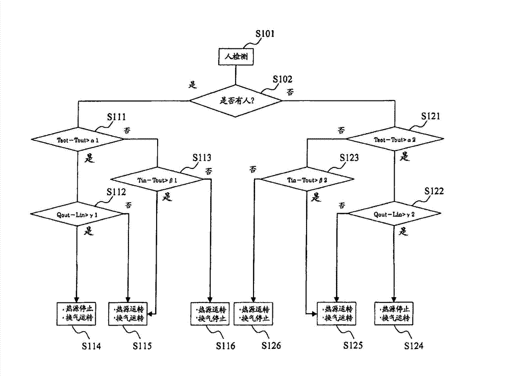
[0019] figure 2 It is a figure which shows the flow of the control operation|movement of the air-conditioning system 100 which concerns on Embodiment 1 of this invention.

[0020] In Embodiment 1, if figure 1 As shown, the air conditioning system 100 is an air conditioning system including an outside air introduction unit 1 , a heat pump air conditioner 2 , a ventilator 3 , a communication line 4 , a human sensor 5 , an indoor temperature sensor 8 and an outdoor temperature sensor 9 .

[0021] The outside air introduction part 1 , the ventilation device 3 , the human sensor 5 , the indoor temperature sensor 8 , and the outdoor temperature sensor 9 are provided in the air-conditioned space 10 . The air-conditioned space 10 is covered with a wall surf...

Embodiment approach 2

[0044] Below, based on image 3 and Figure 4 Embodiment 2 will be described.

[0045] image 3 It is a figure which shows the structure of the air conditioning system 100 which concerns on Embodiment 2 of this invention.

[0046] Figure 4 It is a figure which shows the flow of the control operation|movement of the air-conditioning system 100 which concerns on Embodiment 2 of this invention.

[0047] In addition, the same code|symbol is attached|subjected to the same part as Embodiment 1, and description is abbreviate|omitted.

[0048] In Embodiment 1, the air in the air-conditioned space 10 and the outside air are circulated by providing the outside air introduction part 1 for letting the outside air flow into the air-conditioned space 10 and installing the ventilator 3 for letting the air in the air-conditioned space 10 flow out to the outside. On the other hand, in Embodiment 2, the outside air introduction part 1 and the ventilator 3 are removed, the total heat exchang...


PUM


Abstract

In the present invention, a control device (2a) sets a target temperature for an air-conditioned space (10), compares the value obtained by subtracting from the target temperature an outside temperature detected by an outside temperature sensor (9) and a first threshold relating to that value, compares the value obtained by subtracting the outside temperature from an inside temperature detected by an inside temperature sensor (8) and a second threshold relating to that value, compares the value obtained by subtracting the heat load of the air-conditioned space (10) from the cooling capacity and a third threshold relating to that value, and controls the operation of a heat pump-type air conditioner (2) and a fan device (3) on the basis of these comparison results. The first, second and third thresholds are set in accordance with the number of people detected by a people-detection sensor (5).

Description

technical field [0001] The present invention relates to air conditioning systems. Background technique [0002] As a control device of a conventional air conditioner, there are the following control devices. For example, it is determined whether the room temperature is higher than the set value, and if the room temperature is lower than the set value, by controlling the output from the microcomputer of the indoor unit to the driving transistor (indoor unit side) to be "LO", And the control device that stops the operation of the compressor and the ventilation fan (compressor OFF, ventilation fan OFF). On the other hand, when the room temperature is higher than the set value, the control device transmits an ON signal from the microcomputer of the indoor unit to the microcomputer of the outdoor unit, and controls the transmission from the microcomputer of the outdoor unit to the driving transistor ( The output of the outdoor unit side) becomes "HI", and the operation of the c...

Claims


Application Information

Patent Timeline
IPC IPC(8): F24F11/02F24F13/30
CPCF24F2110/12F24F2140/50F24F11/64F24F2120/10F24F11/30F24F11/70F24F11/77F24F2110/10F24F2140/60F24D15/04Y02B30/70F24F11/56F24F2120/00F24F11/46F24F11/63
Inventor 久保和也
Owner MITSUBISHI ELECTRIC CORP
Why Eureka
Try Eureka