tire testing machine
A testing machine and tire technology, applied in the field of machinery, can solve the problems of engineering tire strength, imprint, vertical stiffness and subsidence without special testing equipment.
- Summary
- Abstract
- Description
- Claims
- Application Information
AI Technical Summary
Problems solved by technology
Method used
Image
Examples
Embodiment 1
[0030] The tire testing machine in the present embodiment is used for static load and vertical rigidity experiment of tire.
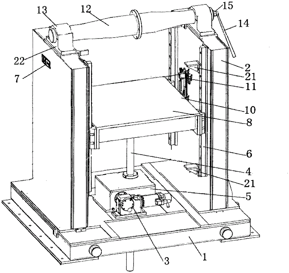
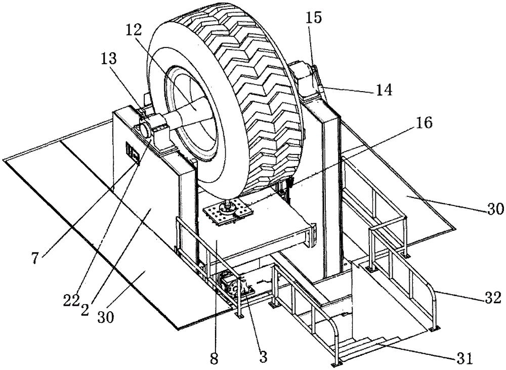
[0031] Such as figure 2 with Figure 4 As shown, the tire testing machine includes a fixing device, a testing device, and a control device. The testing device is driven by a loading device to load the tire on the fixing device.
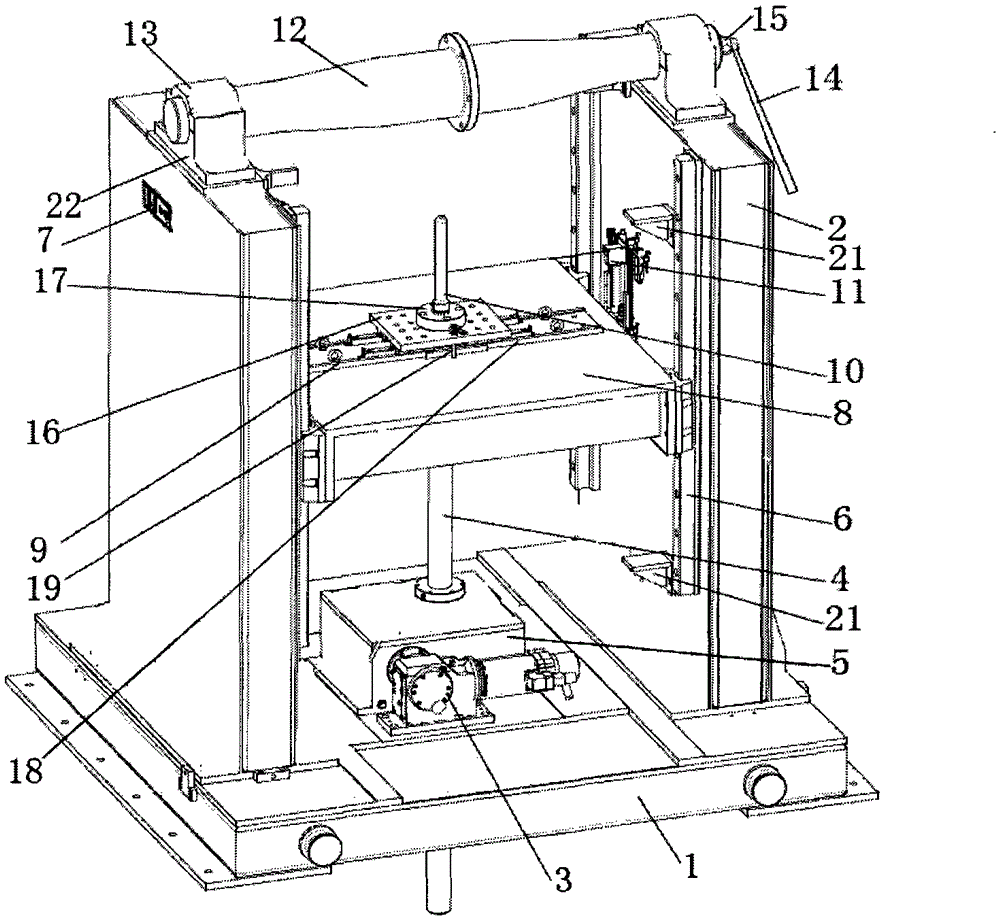
[0032] The loading device includes a servo motor 3, a reducer 5 connected to the servo motor 3, and a ball screw 4 connected to the reducer 5. The ball screw 4 is installed in the output hollow shaft of the reducer 5 through its nut and connected by a flange.
[0033] The fixing device includes a base 1, two vertical walls 2 perpendicular to the base 1, and a rim fixing device between the two vertical walls 2; the vertical walls 2 are parallel to each other, and there are longitudinal linear guide rails 6 parallel to each other inside.
[0034] The rim fixing device spans the tops of the two vertical walls 2;
[0035] The f...
Embodiment 2
[0046] The tire testing machine in the present embodiment is used for static load and impression test of tire.
[0047] Such as figure 2 with Figure 5 As shown, the tire testing machine includes a fixing device, a testing device, and a control device. The testing device is driven by a loading device to load the tire on the fixing device.
[0048] The loading device includes a servo motor 3, a reducer 5 connected to the servo motor 3, and a ball screw 4 connected to the reducer 5. The ball screw 4 is installed in the output hollow shaft of the reducer 5 through its nut and connected by a flange.
[0049] The fixing device includes a base 1, two vertical walls 2 perpendicular to the base 1, and a rim fixing device between the two vertical walls 2; the vertical walls 2 are parallel to each other, and there are longitudinal linear guide rails 6 parallel to each other inside.
[0050] The rim fixing device spans the tops of the two vertical walls 2;
[0051] The fixing part in...
Embodiment 3
[0063] The tire testing machine in this embodiment is used for static load and sidewall deformation experiments of tires.
[0064] Such as figure 2 with Figure 4 As shown, the tire testing machine includes a fixing device, a testing device, and a control device. The testing device is driven by a loading device to load the tire on the fixing device.
[0065] The loading device includes a servo motor 3, a reducer 5 connected to the servo motor 3, and a ball screw 4 connected to the reducer 5. The ball screw 4 is installed in the output hollow shaft of the reducer 5 through its nut and connected by a flange.
[0066] The fixing device includes a base 1, two vertical walls 2 perpendicular to the base 1, and a rim fixing device between the two vertical walls 2; the vertical walls 2 are parallel to each other, and there are longitudinal linear guide rails 6 parallel to each other inside.
[0067] The rim fixing device spans the tops of the two vertical walls 2;
[0068] The fix...
PUM
 Abstract
Description
Claims
Application Information
 - R&D
- Intellectual Property
- Life Sciences
- Materials
- Tech Scout
- Unparalleled Data Quality
- Higher Quality Content
- 60% Fewer Hallucinations
Browse by: Latest US Patents, China's latest patents, Technical Efficacy Thesaurus, Application Domain, Technology Topic, Popular Technical Reports.
© 2025 PatSnap. All rights reserved.Legal|Privacy policy|Modern Slavery Act Transparency Statement|Sitemap|About US| Contact US: help@patsnap.com


