Transmission limit device for soft cable traction video camera

A technology of cable traction and limit device, which is applied in the directions of cameras, supporting machines, mechanical equipment, etc., can solve the problems such as the position of the traction cable driver is not given, the pulley structure is not described, the pulley seat is easily damaged, etc., and it is convenient for assembly. and maintenance, good positioning accuracy, the effect of expanding the scope of application

Inactive Publication Date: 2013-09-11
XIDIAN UNIV
View PDF6 Cites 10 Cited by
  • Summary
  • Abstract
  • Description
  • Claims
  • Application Information

AI Technical Summary

Problems solved by technology

However, the deficiencies that still exist in this patent are: the position of the driver for pulling the cable is not given, and the structure of the pulley at the top of the supporting tower for changing the direction of the cable is not described
But the deficiencies that still exist in this patent are: the structure is still relatively complicated, there is no device for reducing friction at the rotation of the pulley seat, the friction force is relatively large, and the pulley seat is easy to damage

Method used


Image

  • Transmission limit device for soft cable traction video camera
  • Transmission limit device for soft cable traction video camera
  • Transmission limit device for soft cable traction video camera

Examples


Embodiment Construction

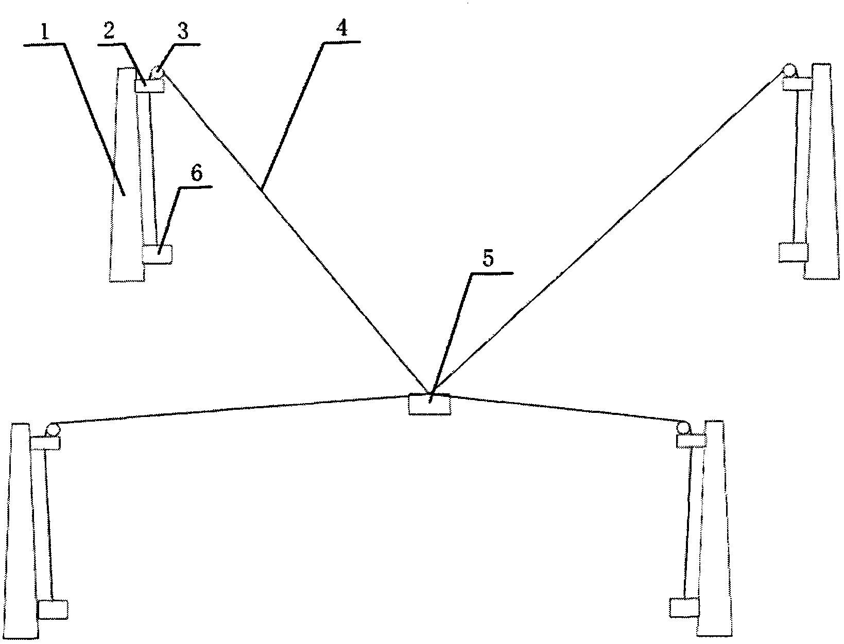
[0017] see figure 1 , flexible cable traction camera transmission limit device of the present invention is made up of support tower column 1, pulley support frame 2, driver 6, block pulley 3, flexible cable 4 and camera 5. There are four supporting towers 1, which are vertically fixed on the ground to form a cuboid space range for the camera 5 to move. The pulley support frame 2, the driver 6 and the pulley block 3 are each four, and a pulley support frame 2 is fixed on the top of each supporting tower column 1 for fixing the pulley block 3; the flexible cable 4 is wound on the driver 6, respectively passing The pulley support frame 2 and the pulley block 3 that respectively support the top of the tower column 1 are connected to the camera 5 together. The driver 6 is fixedly connected to the bottom end of the support tower 1, and the driver 6 is connected to the computer, and the computer controls four drivers 6 to control the retraction and release of the flexible cable 4 at...


PUM


Abstract

A transmission limit device for a soft cable traction video camera comprises four support tower columns, pulley brackets, drivers, pulley sets, soft cables and a video camera. The four support tower columns are perpendicularly fixed on the ground to form a cuboid space for the video camera to move. One pulley bracket is fixed at the top end of each support tower column and used for fixing one pulley set. Each pulley set comprises a base, a pulley, a pulley shaft and a pulley support, wherein the pulley is arranged on the pulley shaft, two ends of the pulley shaft are fixed on two support lugs of the pulley support, and the pulley rotates around the pulley shaft, the base is provided with a frustum, a mounting shaft is arranged at the center of the frustum and provided with a threading hole, a ball is arranged between the frustum and the pulley support, and the pulley support rotates around the mounting shaft, and the two rotation directions are perpendicular to each other. The soft cables wind on the drivers and are jointly connected to the video camera through the pulley brackets and the pulley sets on the support tower columns. The drivers are fixedly connected to the bottom end of the support tower columns and connected with a computer to control winding and unwinding of the soft cables.

Description

technical field [0001] The invention relates to the technical field of mechanical positioning control, and further relates to a precise positioning control device for a cable-tracted camera, specifically a transmission limit device for a cable-tracted camera. Background technique [0002] At present, there are many kinds of robots in the industry that realize the positioning control of space moving objects. The driving devices for realizing the movement of objects are rigid devices such as hydraulic cylinders, air cylinders, electric cylinders, and rotary joints. Some structures use pulleys. The existing pulley is generally composed of a pulley installed on the pulley shaft and placed on the support. The pulley shaft is fixed relative to the support. The direction of rotation of the rope is perpendicular to the pulley shaft. target control. [0003] Garrett W. Brown applied for a patent "A device for supporting and transmitting a suspension system, such as a camera (SUSPENS...

Claims


Application Information

Patent Timeline
Patent Type & Authority Applications(China)
IPC IPC(8): G03B17/56F16M11/18
Inventor 仇原鹰耿争言赵泽段学超苏宇杜敬利段清娟陈光达刘鹏米建伟
Owner XIDIAN UNIV
Why Eureka
Try Eureka