Smart card, controller and adapter

A technology of smart cards and controllers, applied in the field of smart cards, can solve the problems of limited storage space of smart cards and no efficient and economical solutions.

Inactive Publication Date: 2013-09-11
CONTROL TECHN
View PDF4 Cites 2 Cited by
  • Summary
  • Abstract
  • Description
  • Claims
  • Application Information

AI Technical Summary

Problems solved by technology

However, one disadvantage of current smart card technology is that the storage space on the smart card is limited
There is no efficient and cost-effective solution to this problem

Method used


Image

  • Smart card, controller and adapter
  • Smart card, controller and adapter
  • Smart card, controller and adapter

Examples


Embodiment Construction

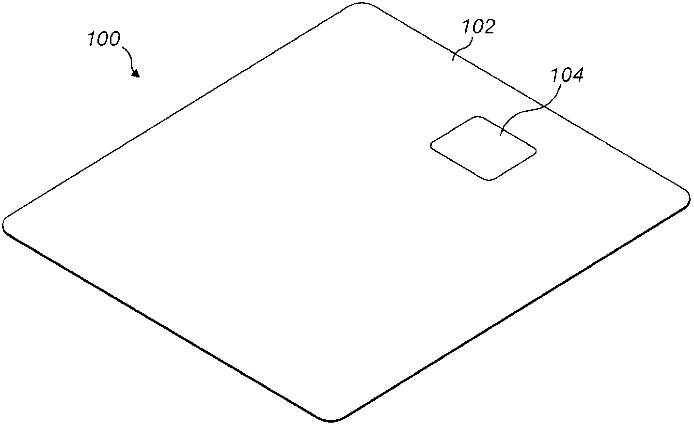
[0037] figure 1 Adapter 100 is shown, comprising a printed circuit board (PCB) having the same appearance and physical specifications as a conventional smart card capable of being used with a conventional smart card reader. For example, adapter 100 may be the same size and shape as a conventional credit card, a utility top-up card, or a user identification / authentication card, depending on the specific use of the adapter 100 .

[0038] The body 102 of the adapter 100 is usually made of plastic, such as polyvinyl chloride (PVC), but other suitable materials can also be used. The adapter comprises an integrated electronic chip 104, the active part of which is embedded in the body 102, wherein the body has an input / output interface visible at least on the upper surface of the adapter 100, preferably as figure 1 The form of the smart card interface shown. The size of the chip 104 and its location on the body 102 of the adapter 100 should be selected based at least in part on the...


PUM


Abstract

The invention discloses a smart card, a controller and an adapter; and the smart card is physically connected with a storage device. The invention simultaneously provides the controller matched with a smart card reader; the controller can be mounted to identify whether the smart card reader is inserted by a normal smart card or an adapter provided with a SD card slot. The controller can be used for controlling communications between the SD card in the SD card slot and the smart card reader, thereby controlling access of the SD card storage.

Description

technical field [0001] The invention relates to a smart card, a controller used in conjunction with a smart card reader, and a secure digital card (SD card) adapter, in particular to reading information stored on the adapter. Background technique [0002] Smart cards are very ubiquitous and have a variety of uses. A smart card (also referred to as a chip card or an integrated circuit card) generally consists of a relatively small (often wallet-sized) card with one or more integrated circuits embedded in it. The integrated circuits on smart cards often include some memory and a microprocessor. Smart cards are often used with smart card readers. Smart card readers typically use data stored on the smart card for user authentication and identification. For example, common smart cards include "chip and pin" credit cards and bank cards. Smart cards can also be used to pay for many goods, including household utility bills, public transport and payphones. Smart cards can also p...

Claims


Application Information

Patent Timeline
IPC IPC(8): G06K19/07G06K7/00
CPCG06K7/0047G06K19/07733G06K19/07737G06K19/07G06K19/07739G06K7/01
Inventor 乔纳森.R.霍尔曼理查德.M.唯恩
Owner CONTROL TECHN
Why Eureka
Try Eureka