Door Lock, System and Method for Remotely Controlled Access

Inactive Publication Date: 2014-01-02
VISCOUNT SECURITY SYST
View PDF9 Cites 192 Cited by
  • Summary
  • Abstract
  • Description
  • Claims
  • Application Information

AI Technical Summary

Benefits of technology

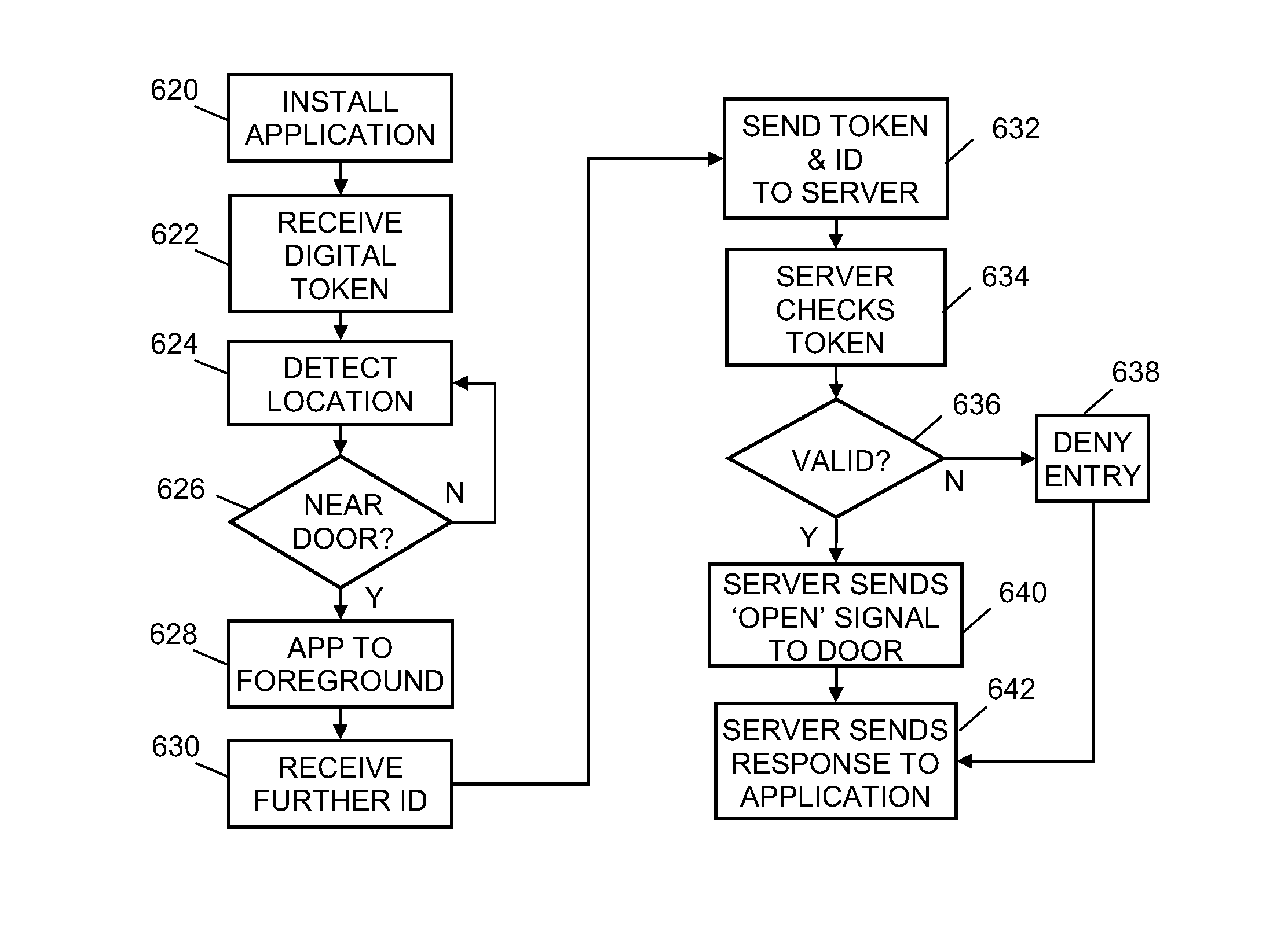
[0016]Disclosed herein is a system for controlling access through doors comprising: a door lock for a door; a powered lock component in the door lock; an unpowered token comprising an identifier for the door lock, said token located in, on or in the vicinity of the door lock; a processor in the door lock configured to receive control instructions and operate the powered lock component; and a server connected to the door lock and configured to generate said control instructions; wherein the server is configured to: receive, from a personal mobile electronic device located in the vicinity of the door lock, the identifier of the door lock and an identification of the personal mobile electronic device; retrieve, from a database storing the identifier, a permission level for a user associated with the identification to open said door lock; and if the permission level indicates that permission is granted, generate a TCP/IP packet comprising an access granted control instruction and send the packet to the door lock, upon which said processor causes the lock component to unlock the door.
[0017]Also disclosed is a method for controlling access through a door comprising: receiving, by a server, from a personal mobile electronic d

Problems solved by technology

Many such door locks have an onboard, externally accessible data port for local programming, which presents a cyber risk as evidenced by recent hacking attacks.
As a result of the disparate control means and separate methods for granting permissions, it is often inconvenient for a user or administrator to access, program and control each security device or system efficiently.
Furthermore, self-contained, on-site security systems o

Method used


Image

  • Door Lock, System and Method for Remotely Controlled Access
  • Door Lock, System and Method for Remotely Controlled Access
  • Door Lock, System and Method for Remotely Controlled Access

Examples


Embodiment Construction

[0050]Throughout the following description, specific details are set forth in order to provide a more thorough understanding of the invention. However, the invention may be practiced without these particulars. In other instances, well known elements have not been shown or described in detail to avoid unnecessarily obscuring the invention. Accordingly, the specification and drawings are to be regarded in an illustrative, rather than a restrictive, sense.

[0051]A software implemented method or process is here, and generally, conceived to be a self-consistent sequence of steps leading to a desired result. These steps require physical manipulations of physical quantities. Often, but not necessarily, these quantities take the form of electrical or magnetic signals capable of being stored, transferred, combined, compared, and otherwise manipulated. It will be further appreciated that the line between hardware and software is not always sharp, it being understood by those skilled in the art...


PUM


Abstract

Secure door entry without a traditional card reader is made possible by tagging the door with an unpowered, unique token which can be read by a user's personal mobile electronic device. The user's device transmits both door and user identification to a remote server, where the decision is made whether to open the door. If so, the server sends an open door signal using the IP suite of protocols to a processor in a powered door lock, opening the door. Another signal may be used indicate whether access is denied or granted. Multiple personal mobile electronic devices may be configured to operate the same door, and users may control access by others.

Description

[0001]This application is a continuation-in-part of and claims the benefit of U.S. patent application Ser. No. 13 / 607,651, filed Sep. 7, 2012, which is a continuation-in-part of and claims the benefit of U.S. patent application Ser. No. 13 / 215,211, filed Aug. 22, 2011, which is a continuation-in-part of and claims the benefit of U.S. patent application Ser. No. 12 / 958,780, filed Dec. 2, 2010, priority from the filing date of which is claimed. The disclosure of said applications are hereby incorporated herein by reference thereto.TECHNICAL FIELD[0002]The present invention generally relates to the field of securing entry through doors and other portals and, more particularly, is concerned with a door lock, system, method and database for controlling and managing access to physical spaces using door identifying tokens and personal mobile devices as readers, via a network that uses the Internet Protocol (IP).BACKGROUND[0003]In many businesses, organizations or public areas, security sys...

Claims


Application Information

Patent Timeline
IPC IPC(8): G08C19/00
CPCG08C19/00G06F21/32G06F21/34G07C9/00309G07C9/00571G07C9/00896G08B25/14G07C9/38H04L63/083H04L63/0861H04L63/102H04W12/06H04W12/77
Inventor PINEAU, STEPHENRAEFIELD, DENNIS
Owner VISCOUNT SECURITY SYST
Why Eureka
Try Eureka