
Bias assembly and manufacturing method thereof, rotating bias field generating device and magnetotherapy instrument

A manufacturing method and technology of rotating magnetic field, applied in the fields of magnetic field generated by permanent magnets, inductance/transformer/magnet manufacturing, permanent magnets, etc., can solve the problems of not being able to meet the needs of use, and not being able to provide targeted treatment by magnets

Inactive Publication Date: 2013-09-11
杭州慈孝堂科技有限公司
View PDF6 Cites 7 Cited by
  • Summary
  • Abstract
  • Description
  • Claims
  • Application Information

AI Technical Summary

Problems solved by technology

[0004] In the above-mentioned prior art, the therapeutic magnetic field provided by the magnetic field generating device for the subject includes both the N-pole magnetic field and the S-pole magnetic field, and the S-pole magnetic field and the N-pole magnetic field are generally balanced. However, most of the current magnetic flux therapy equipment The crowd has key needs, but both are indispensable. For example, some people need rehabilitation treatment, and the demand for negative magnetic field therapy is the focus. Some people need growth promotion treatment, so the demand for positive magnetic field treatment is the focus. In other words, it cannot meet the needs of these people, and cannot provide targeted treatment for the subject.

Method used

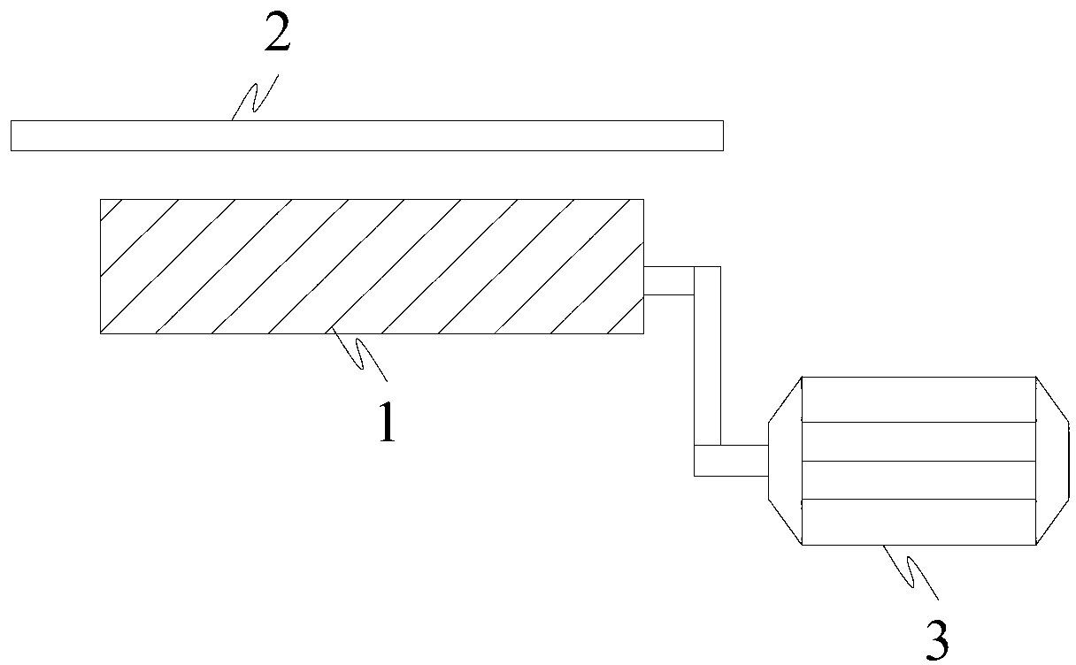
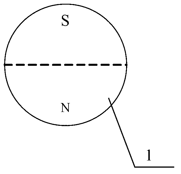

Image

  • Bias assembly and manufacturing method thereof, rotating bias field generating device and magnetotherapy instrument
  • Bias assembly and manufacturing method thereof, rotating bias field generating device and magnetotherapy instrument
  • Bias assembly and manufacturing method thereof, rotating bias field generating device and magnetotherapy instrument

Examples


Embodiment Construction

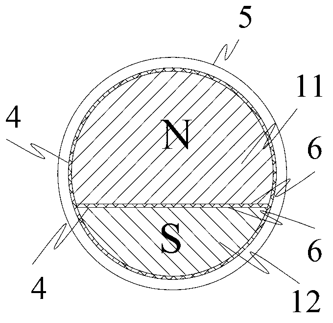
[0022] Such as image 3 As shown, the embodiment of the present invention provides a bias magnetic assembly, which is composed of at least two permanent magnet units with the same magnetic induction intensity, and the permanent magnet units here include image 3 The first permanent magnet unit 11 and the second permanent magnet unit 12 shown in, wherein, the first permanent magnet unit 11 and the second permanent magnet unit 12 are equal in length, and the cross-sectional area of ​​the first permanent magnet unit 11 is greater than that of the second permanent magnet unit The cross-sectional area of ​​the magnet unit 12, and one end of the first permanent magnet unit 11 and the second permanent magnet unit 12 along its length direction is an N pole, and the other end is an S pole; wherein the N pole of the first permanent magnet unit 11 The S pole of the second permanent magnet unit 12 is combined through the split surface 6 , and the S pole of the first permanent magnet unit ...


PUM


Abstract

The invention provides a bias assembly and a manufacturing method, a rotating bias field generating device and a magnetotherapy instrument. The bias assembly is formed by splicing and fixing at least two permanent magnet units identical in magnetic induction intensity, the permanent magnet units are equal in length, the cross section of one of the permanent magnet unit is larger than that of the other permanent magnet unit, one end of each permanent magnet unit along the length direction is an N-electrode, and the other end is an S-electrode. The N-electrode of one of the permanent magnet unit is spliced with the S-electrode of the other permanent magnet unit through a splicing surface, and the S-electrode of one permanent magnet unit is spliced with the N-electrode of the other permanent magnet unit through a splicing surface. Magnetic fields of areas near two ends of the bias assembly are both N-electrode and S-electrode magnetic fields, one end is obvious in characteristics of the N-electrode magnetic fields, the other end is obvious in characteristics of the S-electrode magnetic fields, so bias fields are formed at areas of two ends of the bias assembly respectively, and targeted therapy on human bodies can be realized by the aid of the bias field.

Description

technical field [0001] The invention relates to medical equipment manufacturing technology, in particular to a bias magnetic assembly and its manufacturing method, a rotating bias magnetic field generating device and a magnetic therapy instrument. Background technique [0002] Studies have found that the magnetic field has a significant impact on the human body and other organisms. There are S poles and N poles in the magnetic field at the same time, and the two poles are in a balanced state. Experiments have proved that the S pole magnetic field and the N pole magnetic field have different biological effects. The N pole The magnetic field has a strong function of repairing cells, and the effects of oxidation, alkalization, activation, and excitement are obvious. The S pole magnetic field has the effect of promoting growth and accelerating photosynthesis. Rehabilitation treatment for various diseases, and the strong magnetic field of the S pole actively promotes the growth o...

Claims


Application Information

Patent Timeline
IPC IPC(8): H01F7/02H01F41/02A61N2/06
Inventor 楼中平葛俊
Owner 杭州慈孝堂科技有限公司
Learn More