Sole with novel bulge structure

A hollow structure, bottom surface technology, applied in the direction of soles, footwear, applications, etc., can solve the problems of insufficient, small contact area, easy to break air flow space, etc.

Active Publication Date: 2013-09-18
MAOTAI FUJIAN SOLES CO LTD
View PDF7 Cites 0 Cited by
  • Summary
  • Abstract
  • Description
  • Claims
  • Application Information

AI Technical Summary

Problems solved by technology

[0003] In order to solve the technical problems of the prior art that the bumps or protrusions at the bottom of the soles have a small contact area with the flat road surface or the support per...

Method used


Image

  • Sole with novel bulge structure
  • Sole with novel bulge structure
  • Sole with novel bulge structure

Examples


Embodiment 1

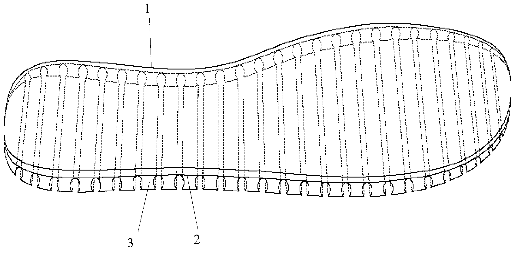
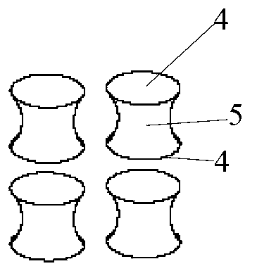
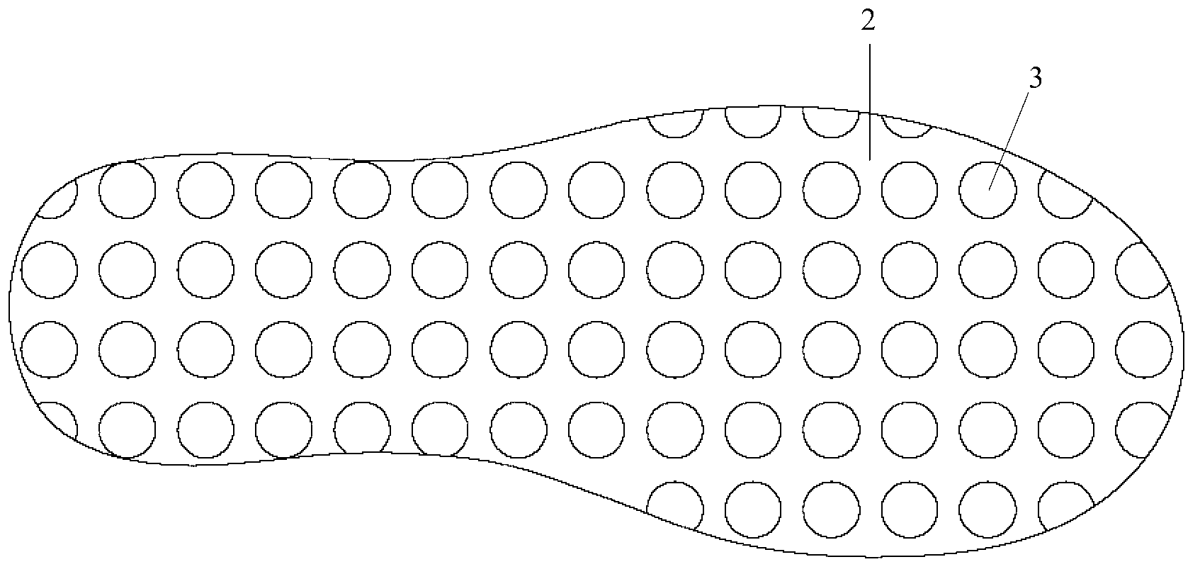
[0042] Such as figure 1 Shown is a schematic diagram of the sole. A sole 1, in figure 1 The shoe sole 1 is shown in , the bottom surface of the shoe sole 2 is provided with several protrusions 3 , and the projections 3 extend from the bottom surface of the shoe sole 2 to the bottom of the shoe sole 1 . Preferably, below the sole 1 here refers to directly below the sole 1; the extension direction of the protrusion 3 includes a contraction section (such as figure 2shown), preferably, the extension direction of the protrusion 3 is perpendicular or approximately perpendicular to the bottom surface of the sole 2, and the contraction section (such as figure 2 (shown) is a waist-like structure shrinking from both ends to the middle cross-sectional area on the extension path of the protrusion 3 . Such as figure 2 Shown is a schematic diagram of several contraction segments. exist figure 2 The two ends 4 of a constriction section and the middle part 5 of the constriction sect...

Embodiment 2

[0044] Such as figure 1 As shown, on the basis of the technical implementation of Example 1, this embodiment further proposes that the shrinkage section is the whole of the protrusion 3, and the shrinkage of the cross-sectional area is a gradual shrinkage of the cross-sectional area. Preferably, the gradual shrinkage can It is understood that the edge of the longitudinal section of the protrusion 3 along the extending direction of the protrusion 3 is a smooth curve.

Embodiment 3

[0046] Such as Figure 8 As shown, on the basis of Embodiment 1, this embodiment further increases air vents 7 on the sole 1, and the sole 1 has air vents 7, and the air vents 7 are arranged outside the protrusions 3 of the sole 1. Partially and through the upper and lower surfaces of the sole 1, because the bottom surface of the sole 2 is raised by the protrusion 3 (such as figure 1 As shown), it is basically possible to prevent sundries from scratching the soles of the feet through the ventilation holes 7, so the size of the ventilation holes 7 can be designed to be larger.


PUM

PropertyMeasurementUnit
Thicknessaaaaaaaaaa

Abstract

The invention provides a sole with a novel bulge structure. The bottom surface of the sole is provided with a bulge array; bulges extend downwards from the bottom surface of the sole; each bulge comprises a contraction section; and each contraction section adopts a waist-shaped structure, of which the cross section area is contracted from both ends to the middle part on the extending path of the corresponding bulge. The sole can be used as a sole of various shoes.

Description

technical field [0001] The present invention relates to shoe soles, in particular to shoe soles with novel raised structures. Background technique [0002] At present, many shoe soles have protrusions on the bottom, such as football shoes, whose studs are used to penetrate the mud surface and bite with the mud to generate grip, and the bumps of the soles of sports shoes, which are made of elastic materials, so that the soles Provides shock absorption properties. The area of ​​the cross-sectional area of ​​the existing first sole bottom protrusion perpendicular to its extension direction tends to shrink from the fixed end of the protrusion to the supporting ground end, so that the protrusion is easier to penetrate the soil surface, or on the contrary, the second type The cross-sectional area of ​​the protrusion at the bottom of the sole perpendicular to its extending direction shrinks from the ground-supporting end to the fixed end to obtain a larger air flow space. The area...

Claims


Application Information

Patent Timeline
IPC IPC(8): A43B13/26A43B13/14
Inventor 丁思博丁思恩郑荣大郑艺文余常彬黄明显
Owner MAOTAI FUJIAN SOLES CO LTD
Why Eureka
Try Eureka