Expansion joint for conductive rail

A technology of expansion joints and conductor rails, applied in the direction of power rails, etc., can solve the problems of the guide plate design without considering the increase of joint stiffness requirements, poor anti-theft performance and anti-vibration performance, and reduced service life of expansion joints. risk, improve anti-theft performance, and debug the effect of simple installation

Active Publication Date: 2013-09-18
NEW UNITED GROUP +1
View PDF7 Cites 10 Cited by
  • Summary
  • Abstract
  • Description
  • Claims
  • Application Information

AI Technical Summary

Problems solved by technology

[0005] (1) The middle rail of the joint does not participate in the electrical connection of the conductor rail, so that when the power receiving shoe is just in the middle rail and does not touch the left and right conductor rails, its current is all obtained through the fishplate and the connection Bolts are provided, resulting in unstable current in the conductor rail and arcing
[0006] (2) The copper electrical conductor has a large contact surface with the aluminum alloy support plate at the bottom of the conductive rail. The direct electrical connection of conductors of different materials will inevitably cause electrochemical corrosion. Long-term electrochemical corrosion will inevitably lead to a decrease in the service life of the expansion joint
[0007] (3) The use of copper electrical conductors is expensive, and at the same time, the bottom support plate of the conductive rail is connected by bolts, so the anti-theft performance and anti-vibration performance are poor
[0009] (1) The installation accuracy is required to be high. When there is a deviation in the coaxiality between the cylindrical rigid guide rail and the sleeve-shaped electrical connector, stagnation will occur
[0010] (2) The design of the guide plate does not consider the requirement to increase the stiffness of the joint. When the joint is deflected due to gravity or the pressure of the electric shoe, the cylindrical rigid guide rail and the sleeve-shaped electrical connector will bear bending stress, which directly affects its sliding performance
[0011] (3) The contact surface formed by the cylindrical rigid guide rail and the sleeve-shaped electrical connector is restricted by various factors such as manufacturing accuracy, installation accuracy and external environmental pollution, and the contact resistance is large and difficult to maintain stability

Method used


Image

  • Expansion joint for conductive rail
  • Expansion joint for conductive rail
  • Expansion joint for conductive rail

Examples


Embodiment Construction

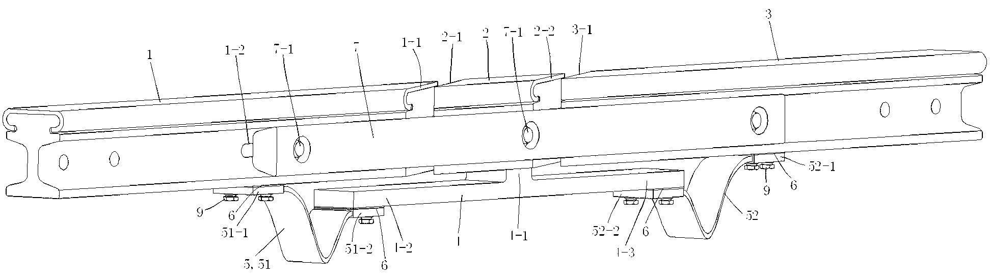
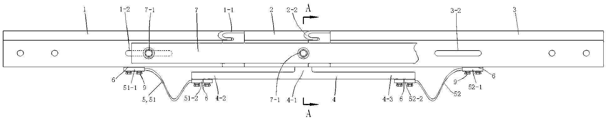
[0034] see Figure 1 to Figure 6 A conductive rail expansion joint shown includes a left conductive rail 1, a middle rail 2 and a right conductive rail 3; 2 and the left end surface 3-1 of the right conductive rail 3 are mutually parallel slopes, the expansion joint also includes a conductive plate 4 and a wire 5; the conductive plate 4 has a boss portion 4-1, and the convex portion of the conductive plate 4 The table portion 4-1 is fixedly connected to the bottom surface of the middle rail 2, and the left and right ends 4-2 and 4-3 of the conductive plate 4 are suspended; the wire 5 is divided into a left wire 51 and a right wire 52, and the left wire 5 One end 51-1 of the wire 51 is connected to the bottom surface of the left conductive rail 1, the other end 51-2 of the left wire 51 is connected to the left suspension end 4-2 of the conductive plate 4, and one end 52-2 of the right wire 52 1 is connected to the bottom surface of the right conductive rail 3, and the other en...


PUM


Abstract

The invention discloses an expansion joint for a conductive rail. The expansion joint for the conductive rail comprises a left conductive rail, a middle rail and a right conductive rail, wherein the right end face of the left conductive rail, the two end faces of the middle rail and the left end face of the right conductive rail are mutually-parallel inclined planes; the expansion joint further comprises a conductive plate and wires; the conductive plate is provided with a boss part fixedly connected to the bottom surface of the middle rail; the left end and the right end of the conductive plate are suspended; the wires consist of a left wire and a right wire; one end of the left wire is connected to the bottom surface of the left conductive rail, and the other end is connected to the suspended left end of the conductive plate; one end of the right wire is connected to the bottom of the right conductive rail, and the other end is connected to the suspended right end of the conductive plate; the wires keep in a relax state after being connected; and the expansion joint further comprises a copper-aluminum transition plate. The expansion joint provided by the invention has a simple structure, is excellent in pickproof and shock-resistant performance, can effectively ensure requirements of follow current and current carrying on the expansion joint, and can ensure constant and reliable current capacity.

Description

technical field [0001] The invention relates to a power supply system for rail transit electric vehicles, in particular to a conductive rail expansion joint in the rail transit electric vehicle power supply system, and belongs to the technical field of electric rails. Background technique [0002] With the rapid development of urban rail transit, steel-aluminum composite conductive rail (referred to as the third rail) has gradually become the first choice for urban rail transit power supply system due to its unique advantages, and the main rail of steel-aluminum composite conductive rail and its accessories are also constantly be improved. [0003] When laying conductor rails, a telescopic expansion joint must be installed between two adjacent conductor rails to overcome the thermal expansion and contraction of the conductor rails as the temperature changes. The expansion joint is required to have the characteristics of small contact resistance, good reliability and conveni...

Claims


Application Information

Patent Timeline
Patent Type & Authority Applications(China)
IPC IPC(8): B60M1/30
Inventor 彭高军房丽婷须晓强
Owner NEW UNITED GROUP
Why Eureka
Try Eureka