
High-stability slide switch

A sliding switch, high-stability technology, used in electrical switches, electrical components, circuits, etc., can solve the problems of melting of the end of the moving contact, small adaptability, low stability, etc., to reduce the number of parts, improve installation efficiency, The effect of improving stability

Pending Publication Date: 2021-01-29
SUZHOU HUAZHIJIE TELECOM
View PDF0 Cites 0 Cited by
  • Summary
  • Abstract
  • Description
  • Claims
  • Application Information

AI Technical Summary

Problems solved by technology

[0002] Sliding switch is a kind of switch commonly used in electrical equipment, especially electric tools. The moving contact piece inside the traditional sliding switch adopts a seesaw connection method in which one end touches a static terminal and the other end is connected with a reed. This kind of moving contact The advantage of the contact plate is that it moves quickly and is not easy to arc, but because the moving contact plate needs to swing, the actual contact area between the end of the moving contact plate and the static terminal and the static terminal is very small, resulting in a large resistance at this point and heat generation. Large, so the current-carrying capacity is poor. If it is applied to a higher current, it will easily cause the end of the moving contact to melt and catch fire. Therefore, the traditional seesaw slide switch has a small range of application and low stability.

Method used


Image

  • High-stability slide switch
  • High-stability slide switch

Examples


Embodiment Construction

[0016] Specific embodiments of the present invention will be described in detail below in conjunction with the accompanying drawings.

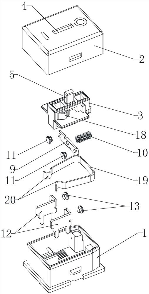
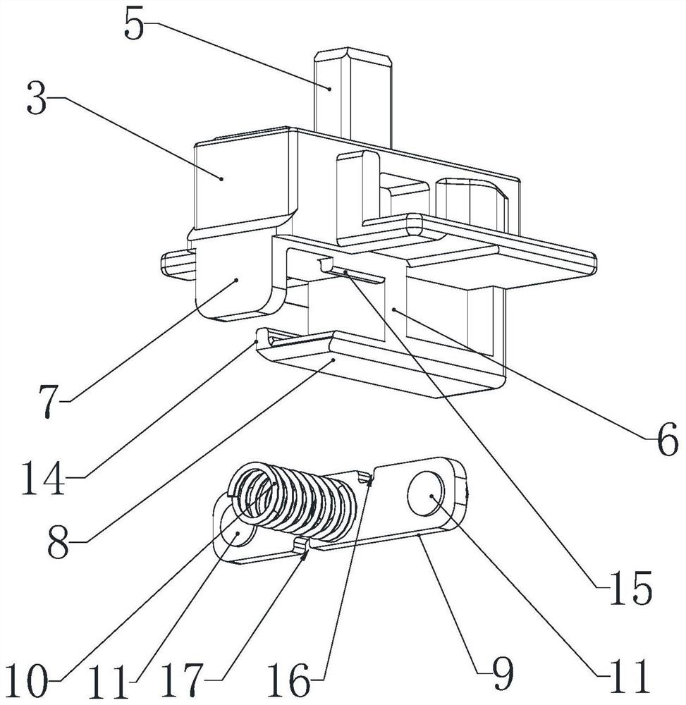
[0017] Such as figure 1 The high-stability slide switch shown includes a base 1 and an upper cover 2 that covers the base 1. The base 1 and the upper cover 2 form a hollow shell, and a slider is slidably connected inside the base 1. 3. There is a long hole 4 extending along the sliding direction of the slider 3 on the upper cover 2, the upper end of the slider 3 is connected with a dial handle 5, and the upper end of the dial handle 5 protrudes out of the upper cover 2 through the long hole 4, and pushes the dial The handle 5 can control the sliding block 3 to slide back and forth in the base 1 . Such as figure 2 As shown, the bottom of the slider 3 is vertically connected with a first baffle 6 and a second baffle 7 facing each other and arranged along the sliding direction of the slider 3, wherein the lower end of the first baffle 6 is con...


PUM


Abstract

The invention relates to a high-stability sliding switch. The switch comprises a base and an upper cover, a sliding block is slidably connected into the base, a first baffle and a second baffle whichare opposite to each other and arranged in the sliding direction of the sliding block are perpendicularly connected to the bottom of the sliding block, and a supporting plate extending towards the second baffle is connected to the lower end of the first baffle. The length of the supporting plate is smaller than the distance between the first baffle and the second baffle, a movable contact piece and a spring are clamped between the first baffle and the second baffle, the movable contact piece is attached to the first baffle under the elastic action of the spring, the supporting plate is supported below the movable contact piece and the spring, and the two ends of the movable contact piece extend out of the first baffle and are provided with movable contacts. Two static contact pieces are arranged in the base, static contacts in one-to-one correspondence with the two movable contacts are arranged on the two static contact pieces respectively, the spring and the static contacts are arranged on the two sides of the movable contact pieces respectively, and when the sliding block slides to the static contacts, the movable contacts abut against the static contacts and compress the spring,and the switch is closed and slides.

Description

technical field [0001] The invention relates to a high-stability slide switch. Background technique [0002] Sliding switch is a kind of switch commonly used in electrical equipment, especially electric tools. The moving contact piece inside the traditional sliding switch adopts a seesaw connection method in which one end touches a static terminal and the other end is connected with a reed. This kind of moving contact The advantage of the contact plate is that it moves quickly and is not easy to arc, but because the moving contact plate needs to swing, the actual contact area between the end of the moving contact plate and the static terminal and the static terminal is very small, resulting in a large resistance at this point and heat generation. Large, so the current-carrying capacity is poor. If it is applied to a higher current, it will easily cause the end of the moving contact to melt and catch fire. Therefore, the traditional seesaw slide switch has a small range of ap...

Claims


Application Information

Patent Timeline
IPC IPC(8): H01H15/24H01H15/04H01H15/06H01H15/16
CPCH01H15/04H01H15/06H01H15/16H01H15/24
Inventor 吴世明
Owner SUZHOU HUAZHIJIE TELECOM
Learn More