Detachable upright post type steel structure for internal combustion locomotive cooling chamber

A technology for diesel locomotives and steel structures, applied to locomotives, etc., can solve the problems of difficult installation and removal of large parts in the cooling chamber of locomotives, and achieve the effect of convenient installation and saving installation time

Active Publication Date: 2013-09-18
CRRC QISHUYAN CO LTD
View PDF6 Cites 5 Cited by
  • Summary
  • Abstract
  • Description
  • Claims
  • Application Information

AI Technical Summary

Problems solved by technology

[0002] Generally, the steel structure columns and diagonal braces in the cooling room of diesel locomotives are non-detachable, and the large parts installed inside the cooling room need to be hoisted from the upper part of the steel structure for maintenance during the maintenance and disassembly process, which requires removal of the upper part of the steel structure. components, causing difficulties in the installation and removal of large components in the cooling chamber of the locomotive

Method used


Image

  • Detachable upright post type steel structure for internal combustion locomotive cooling chamber
  • Detachable upright post type steel structure for internal combustion locomotive cooling chamber
  • Detachable upright post type steel structure for internal combustion locomotive cooling chamber

Examples


Embodiment Construction

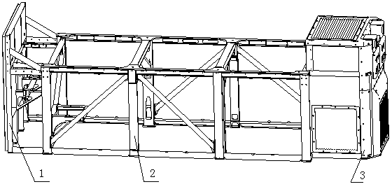
[0018] Such as figure 1 As shown, a cooling chamber steel structure of a diesel locomotive with a detachable column includes three parts: the front steel structure 1, the main steel structure 2 of the cooling chamber and the steel structure 3 of the resistance brake chamber. The three parts are sequentially connected by welding.

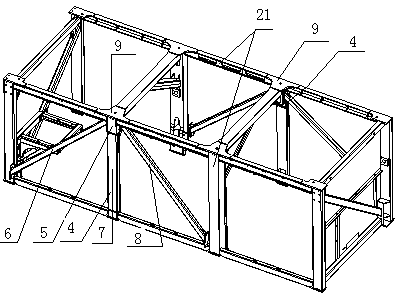
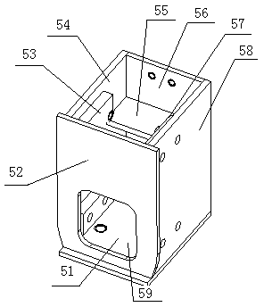
[0019] Such as figure 2 As shown, the left and right sides of the main steel structure 2 of the cooling chamber are provided with movable side frame assemblies 4, and the side frame assemblies 4 include connecting devices 5, detachable column one 6, detachable column two 7 and The detachable column three 8, the connection device 5 is installed on the side frame 21 of the main steel structure 2 of the cooling chamber, the detachable column two 7 is installed under the bottom plate 51 of the connection device 5, the detachable column one 6 and the detachable column three 8 are respectively Installed on both sides of the connection device 5, the conne...


PUM


Abstract

The invention relates to the technical field of internal combustion engine mechanical structures, and particularly relates to a detachable upright post type steel structure for an internal combustion locomotive cooling chamber. The detachable upright post type steel structure comprises three parts including a front steel structure, a cooling chamber primary steel structure and a resistance braking chamber steel structure, wherein the three parts are connected in sequence in a welding manner; the left side and the right side of the cooling chamber primary steel structure are provided with movable side frame assemblies; each side frame assembly comprises a connecting device, a detachable upright post I, a detachable upright post II and a detachable upright post III; the connecting device is arranged on a side frame of the cooling chamber primary steel structure; the detachable upright post II is arranged below a bottom plate of the connecting device; the detachable upright post I and the detachable upright post III are respectively arranged on both sides of the connecting device; and a stable triangular supporting structure is formed by the connecting device, the detachable upright post I, the detachable upright post II and the detachable upright post IIII. The detachable upright post type steel structure effectively solves the space problems of installation and maintenance of large components inside the internal combustion locomotive cooling chamber, brings great convenience for installation of the large components, and saves the time of installation.

Description

technical field [0001] The invention relates to the technical field of mechanical structures of internal combustion engines, in particular to a steel structure for a cooling chamber of a diesel locomotive with detachable columns. Background technique [0002] Generally, the steel structure columns and diagonal braces in the cooling room of diesel locomotives are non-detachable, and the large parts installed inside the cooling room need to be hoisted from the upper part of the steel structure for maintenance during the maintenance and disassembly process, which requires removal of the upper part of the steel structure. Parts, causing difficulties in the installation and removal of large parts in the cooling chamber of the locomotive. Contents of the invention [0003] In order to make the large parts inside the cooling chamber can be placed and taken out smoothly during installation and maintenance, and to avoid disassembly and assembly of the upper parts of the cooling cha...

Claims


Application Information

Patent Timeline
Patent Type & Authority Applications(China)
IPC IPC(8): B61C17/00
Inventor 高科伟管敏玮肖腾
Owner CRRC QISHUYAN CO LTD
Why Eureka
Try Eureka