Anti-dumping valve

A technology of anti-dumping and dumping valves, which is applied in the direction of adding non-fuel substances, engine components, liquid fuel feeders, etc. to the fuel to achieve the effects of high safety, improved dimensional accuracy, and improved production efficiency

Active Publication Date: 2013-09-18
SUZHOU YUANNENG DONGLI TECH CO LTD
View PDF4 Cites 3 Cited by
  • Summary
  • Abstract
  • Description
  • Claims
  • Application Information

AI Technical Summary

Problems solved by technology

[0007] Aiming at the deficiencies in the prior art, the present invention provides an anti-dumping valve, which solves the safety hazards of accidental closing or accidental leakage of the anti-dumping valve through targeted structural improvement; by changing the gap between the valve seat and the valve body The connection method improves the dimensional accuracy and production efficiency

Method used


Image

  • Anti-dumping valve
  • Anti-dumping valve
  • Anti-dumping valve

Examples


Embodiment 1

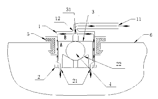
[0038] combine figure 2 As shown, in an anti-dumping valve of the present invention, the valve body 1 and the valve seat 2 are buckled to form a valve chamber B, and the top of the valve body 1 is integrally provided with a first vent 11, and the first vent 11 and the valve chamber B pass through the valve The port 12 is connected, and the center of the bottom of the valve seat 2 is integrally provided with a conical pit 22, and a cross groove can be provided in the longitudinal direction of the conical pit 22;

[0039] A cover-shaped float 3 is arranged above the valve seat 2, and a valve core 31 that cooperates with the valve port 12 and can close the first vent port is provided on the top outside of the float 3. The valve core 31 and the valve port 12 can be in contact with a spherical surface. It can also be contacted with a rounded surface, and the line contact can ensure the tightness of the valve closing. The conical structure can ensure that it can be effectively rese...

Embodiment 2

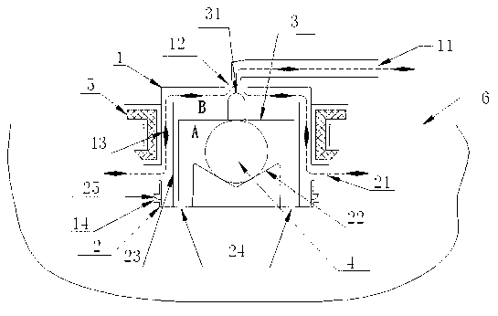
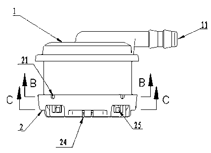
[0046] combine Figure 2 to Figure 11 As shown, an anti-dumping valve, on the basis of the structure of Embodiment 1, the number of the second air vent 21, the liquid discharge port 24, the number of fastening holes 14, and the number of fastening bosses 25 are all set to four, as a kind of implementation.

Embodiment 3

[0048] combine Figure 12 As shown, another implementation of the anti-dumping valve is based on Example 1, and on the basis of retaining the structural design of setting the isolation cylinder 23 in the valve and setting the second vent 21 on the side, the valve The body 1 and the valve seat 2 are connected in the form of welding instead of the connection method of the elastic snap-fit ​​structure. It can also achieve the effect of keeping the fuel tank pressure in a safe range all the time during work, and has the effect of preventing accidental leakage of fuel through the anti-dump valve.


PUM


Abstract

The invention discloses an anti-dumping valve. A valve body (1) is connected with a valve seat (2) to form a valve cavity (B); a cover-shaped floater (3) is arranged above the valve seat (2); a steel ball (4) which can move freely and allow the floater (3) to move up and down in the valve cavity (B) is placed between the floater (3) and the valve seat (2); a rubber sealing ring (5) is mounted on an external wall of the valve body (1) in an embedded manner; a mounting surface of the rubber sealing ring (5) is higher than the valve seat (2); in addition, an outer ring of the floater (3) is provided with an isolation cylinder (23) protruding upwards from the bottom of the valve seat (2); a second air vent (21) is formed close to the lower edge of the rubber sealing ring (5); and the valve body (1) is connected with the valve seat (2) by an elastic buckled structure perferably. According to the anti-dumping valve, since the isolation cylinder is adopted, and the position of the second air vent is changed, accident closing of the anti-dumping valve can be avoided, the anti-dumping valve has a better leakproof effect; and with the adoption of the elastic buckled mode, the dimensional precision and production efficiency are improved.

Description

technical field [0001] The invention relates to a mechanical valve, especially a breather valve installed on a fuel oil tank of a general gasoline engine to prevent fuel oil from dumping. Background technique [0002] In the prior art, the breather valve installed on the general gasoline engine fuel oil tank (such as figure 1 As shown), the valve cavity is sealed by the valve body and the valve seat. There is a first vent on the top of the cavity, which communicates with the valve cavity through a valve port. The upper end of the valve seat is provided with a conical pit. , There is a cap-shaped float above the valve seat, and a valve core that cooperates with the valve port to close the first vent is provided on the outside of the top of the float. A steel ball is placed between the float and the valve seat. When the anti-dumping valve tilts After reaching a certain angle, the steel ball moves and makes the float move up and down along the inner wall of the valve, and ther...

Claims


Application Information

Patent Timeline
Patent Type & Authority Applications(China)
IPC IPC(8): F02M37/00F02M25/08
Inventor 朱正华
Owner SUZHOU YUANNENG DONGLI TECH CO LTD
Why Eureka
Try Eureka