Fuel injector

A technology of fuel injectors and fuels, which is applied in the direction of fuel injection devices, special fuel injection devices, charging systems, etc., and can solve problems such as complex removal of matching pins, breaking or shearing, and damage to matching pins

Active Publication Date: 2013-09-18
MAN ENERGY SOLUTIONS SA
View PDF6 Cites 2 Cited by
  • Summary
  • Abstract
  • Description
  • Claims
  • Application Information

AI Technical Summary

Problems solved by technology

[0004] However, the fitting pin has the disadvantage that it is easily broken or sheared off due to mechanical overload during assembly or disassembly of the fuel injector, which often necessitates complex repair work at the individual components, especially in view of the number of damaged fitting pins. take out
[0005] A further disadvantage of the dowel pins is that, since the dowel pin holes accommodating the dowel pins are generally introduced into the sealing surfaces between the components, from which the dowel pins protrude after their assembly, it is only necessary for reprocessing (e.g. grinding) of the sealing surfaces Complicated removal of mating pins

Method used


Image

  • Fuel injector
  • Fuel injector
  • Fuel injector

Examples


Embodiment Construction

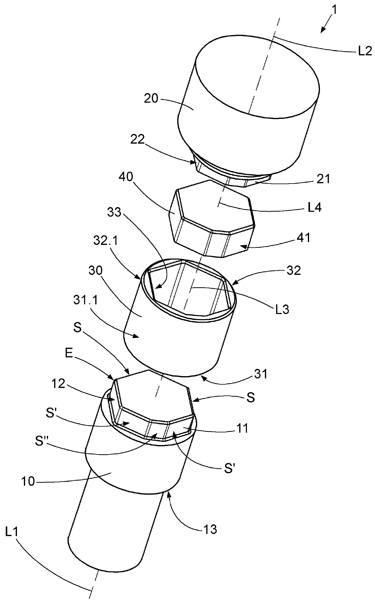
[0072] figure 1 A perspective exploded view of a fuel injector 1 designed according to a first embodiment of the invention of an internal combustion engine (not shown in its entirety), here designed as a marine diesel engine, is shown.

[0073] The fuel injector 1 has an injection nozzle 10 for injecting fuel (here diesel), a switching valve 20 for controlling (enabling / blocking) the injection of fuel and a connecting sleeve arranged between the injection nozzle 10 and the switching valve 20 barrel or centering sleeve 30.

[0074] The injection nozzle 10 has a predetermined nozzle outer contour 12 at its longitudinal end section 11 facing the connecting sleeve 30 , while the switching valve 20 has a predetermined nozzle outer contour 12 at its longitudinal end section 21 facing the connecting sleeve 30 . Determined valve outer contour 22 .

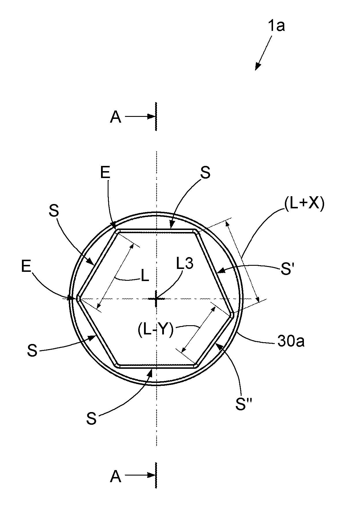
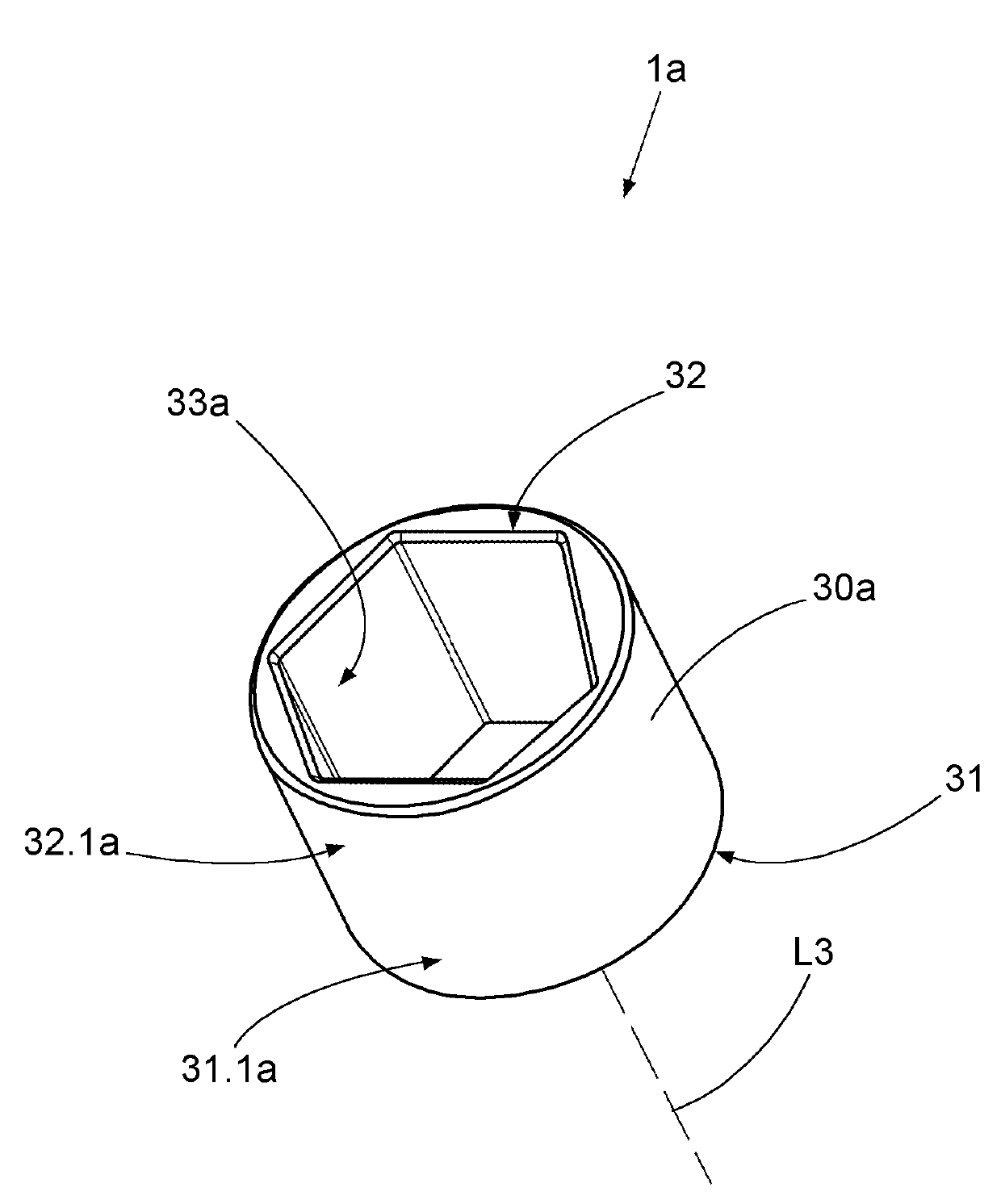
[0075] The connecting sleeve 30 has, for its part, a predetermined inner sleeve contour 33 , into which the spray nozzle 10 with its no...


PUM


Abstract

The invention relates to a fuel injector (1) comprising an injection nozzle (10), a switching valve (20) and a connecting sleeve (30) that is arranged between the injection nozzle (10) and the switching valve (20), wherein the injection nozzle has a predetermined outer nozzle contour (12) on a longitudinal end section (11) thereof and the switching valve has a predetermined outer valve contour (22) on a longitudinal end section (21) thereof, and wherein the connecting sleeve has a predetermined inner sleeve contour (33) into which, from a first longitudinal end (31) of the connecting sleeve, the injection nozzle fits with the outer nozzle contour thereof in a form-fitting manner such that the injection nozzle is fixed in a defined alignment relative to the connecting sleeve, and into which, from a second longitudinal end (32) of the connecting sleeve, the switching valve fits with the outer valve contour thereof in a form-fitting manner such that the switching valve is fixed in a defined alignment to the connecting sleeve.

Description

technical field [0001] The invention relates to a multi-part fuel injector for an internal combustion engine. Background technique [0002] Internal combustion engines known from practice, such as marine diesel engines, have a plurality of cylinders, each of which is associated with at least one fuel injector in order to supply the corresponding cylinder with fuel. Such fuel injectors are usually constructed from a plurality of longitudinally successively assembled parts or components which must be fixed or defined relative to one another in a certain orientation, for example with regard to their longitudinal axis and their rotational position. [0003] In fuel injectors known from practice, these alignments of the components relative to one another are achieved by means of so-called mating pins, which engage into mating pin bores of the components. Such a multi-part fuel injector is known, for example, from DE 2 309 134 A, in which the nozzle structure is oriented relative...

Claims


Application Information

Patent Timeline
Patent Type & Authority Applications(China)
IPC IPC(8): F02M61/18
CPCF02M61/168F02M2200/8015F02M2200/851F02M61/14F02M61/00F02M61/16F02M63/00
Inventor S.柯恩H.韦伦克特W.韦勒
Owner MAN ENERGY SOLUTIONS SA
Why Eureka
Try Eureka