Faucet spool

A faucet and spool technology, applied in the direction of sliding valves, valve devices, engine components, etc., can solve the problems of aggravating the production cost of faucets, user use costs, waste of resources, etc., to achieve convenient implementation, reduce the use of materials, and reduce production cost effect

Active Publication Date: 2015-08-19
KAIPING SEDAL TAP COMPONENTS
View PDF5 Cites 0 Cited by
  • Summary
  • Abstract
  • Description
  • Claims
  • Application Information

AI Technical Summary

Problems solved by technology

[0002] At present, faucet manufacturers are all using the same type of spool to install on single-cooled faucets, refer to Figure 1~Figure 3 This type of spool separates the installation threaded portion 31 ′ on the spool body 3 ′ from the water outlet 32 ​​′, that is, the water outlet 32 ​​′ is arranged below the installation threaded portion 31 ′, so that the head of the spool (O The part above the O-ring 1') is short, and the valve body (the part below the O-ring 1') is long, which makes the installation position of the spool on the main body 2' of the faucet must be designed to be deep, and considering the entire For the beautiful appearance and decorative effect of the faucet, the main body 2' of the faucet must be enlarged to be magnificent, which increases the production cost of the faucet and the use cost of the user, and also causes a certain waste of resources

Method used


Image

  • Faucet spool
  • Faucet spool
  • Faucet spool

Examples


Embodiment Construction

[0014] The present invention will be described in further detail below in conjunction with the accompanying drawings and embodiments.

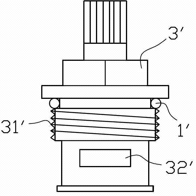
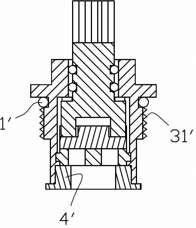
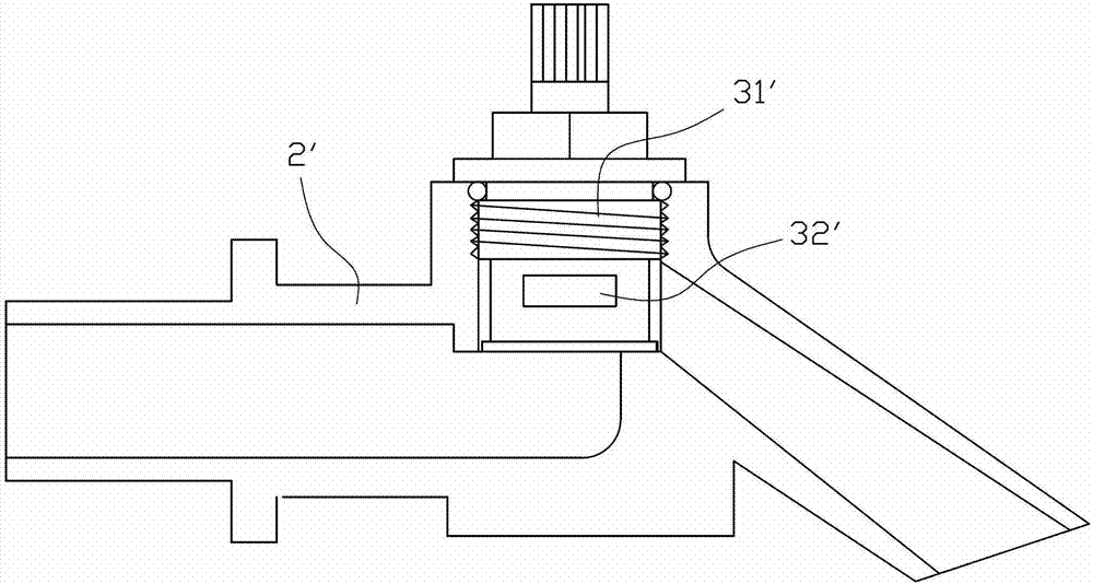
[0015] refer to Figure 4~Figure 6 , the faucet spool of the present invention includes a spool body 1, a rotating rod 2, a moving valve piece 3 and a fixed valve piece 4 installed in the spool body 1 sequentially from top to bottom, and the moving valve piece 3 is fixed At the bottom of the rotating rod 2, the movable valve plate 3 can follow the rotation of the rotating rod 2 to open or close the water inlet and outlet on the fixed valve plate 4. One side acts on the fixed valve plate 4, and the other side acts on the bottom of the valve core installation position of the faucet main body 7, thereby playing the role of sealing and closing the water. The side wall of the valve core body 1 is provided with a mounting thread part 11 and an outlet The nozzle 12 and the mounting thread part 11 are used to install the valve core in the valve core ...


PUM


Abstract

The invention discloses a faucet valve core which comprises a valve core body, a rotary rod, a movable valve plate and a stationary valve plate, wherein the rotary rod, the movable valve plate and the stationary valve plate are mounted in the valve core body sequentially from the top down; the movable valve plate is fixed at the bottom end of the rotary rod; a waterstop rubber ring is arranged at the bottom end of the valve core body; a mounting thread part and a water outlet are arranged on and formed in a side wall of the valve core body; an O-shaped sealing ring is arranged above the mounting thread part; the position of the water outlet on the valve core body is unchanged; the axial height of the mounting thread part is unchanged; the position of the O-shaped sealing ring relative to the mounting thread part is unchanged; the mounting thread part is moved down to allow the water outlet to be located on the mounting thread part; a structure that the water outlet is formed below the mounting thread part in the prior art is abandoned; the valve body length of the valve core is reduced; a valve core mounting position matched with the valve core is designed to be shallow certainly; the gorgeous and attractive decoration effect can be reached under the condition that an entire main body of a faucet is not required to be large; the material consumption is reduced; and the cost is lowered.

Description

technical field [0001] The invention relates to a faucet valve core. Background technique [0002] At present, faucet manufacturers are all using the same type of spool to install on single-cooled faucets, refer to Figure 1~Figure 3 This type of spool separates the installation threaded portion 31 ′ on the spool body 3 ′ from the water outlet 32 ​​′, that is, the water outlet 32 ​​′ is arranged below the installation threaded portion 31 ′, so that the head of the spool (O The part above the O-ring 1') is short, and the valve body (the part below the O-ring 1') is long, which makes the installation position of the spool on the main body 2' of the faucet must be designed to be deep, and considering the entire For the aesthetic appearance and decorative effect of the faucet, the main body 2' of the faucet must be enlarged to be magnificent, which increases the production cost of the faucet and the use cost of the user, and also causes a certain waste of resources. Contents o...

Claims


Application Information

Patent Timeline
Patent Type & Authority Patents(China)
IPC IPC(8): F16K3/06F16K3/30
Inventor 何祺晃
Owner KAIPING SEDAL TAP COMPONENTS
Why Eureka
Try Eureka