Supercharge Your Innovation With Domain-Expert AI Agents!

Portable thermoelectric power generation lighting device

A technology of thermoelectric power generation and lighting device, applied in the field of lighting, can solve problems such as failure to meet actual use requirements, low thermoelectric power generation efficiency, and bulky lighting device, so as to improve market practicability, save power resources, and improve lighting efficiency. Effect

Active Publication Date: 2013-09-18
DONGGUAN HEWANG ELECTRIC CO LTD
View PDF5 Cites 14 Cited by
  • Summary
  • Abstract
  • Description
  • Claims
  • Application Information

AI Technical Summary

Problems solved by technology

This kind of thermoelectric power generation lighting device in the prior art generally has the following major technical problems: low thermoelectric power generation efficiency and low power generation, mainly caused by the small and unstable temperature difference on both sides of the thermoelectric power generation sheet, which also restricts the development of this technology The main problem in the prior art is that there is almost no solution in this regard, that is, a solution that can permanently maintain a large temperature difference between the two ends of the thermoelectric power generation sheet, which makes the lighting of the thermoelectric power generation lighting device in the prior art almost unrealistic. Use requirements, and the instability of this temperature difference also makes it difficult to provide stable lighting output in actual lighting use. There have also been some improvements in this regard by using large-volume radiators to ensure temperature differences, but this The improvement will make the entire lighting device bulky, and the cost performance is not as good as direct electric lighting

Method used


Image

  • Portable thermoelectric power generation lighting device
  • Portable thermoelectric power generation lighting device
  • Portable thermoelectric power generation lighting device

Examples


Embodiment Construction

[0038] The technical solutions of the present invention will be described in detail below in conjunction with the accompanying drawings, so that those skilled in the art can understand the present invention more clearly, but the protection scope of the present invention is not limited thereby.

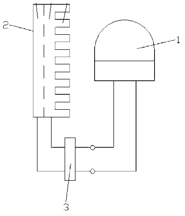
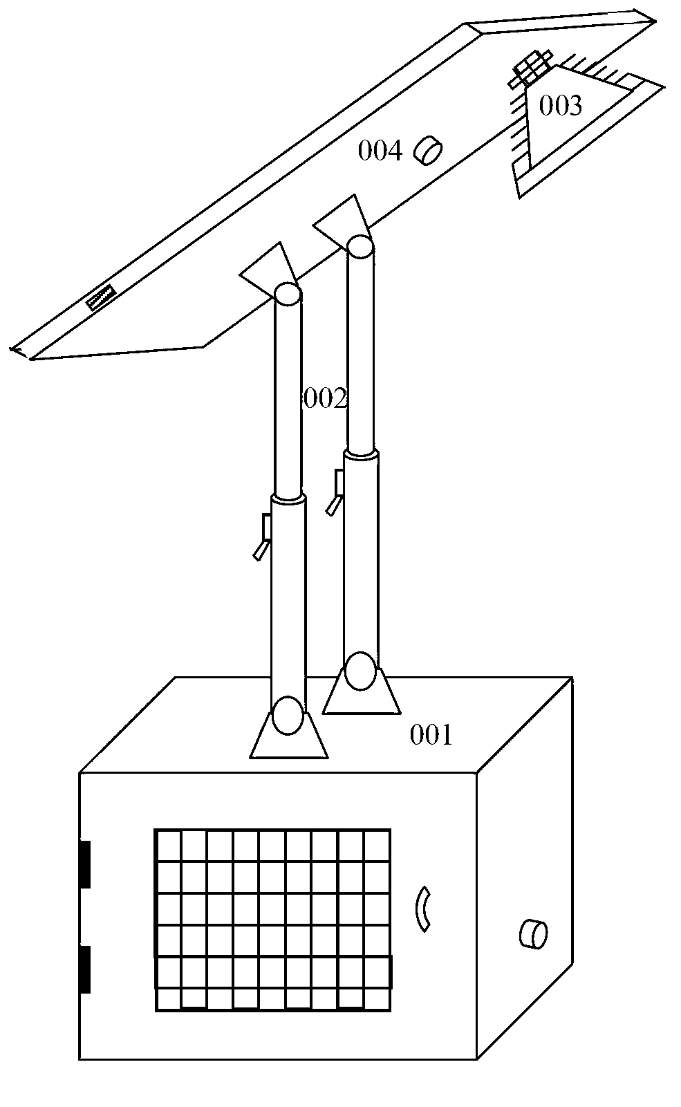
[0039] as attached figure 2 As shown, the thermoelectric power generation lighting device of the present invention as a whole includes a thermoelectric power generation module 001, an adjustment rod 002, a light emitting unit 003 and an installation top plate 004, wherein the light emission unit 003 is installed on the surface of the installation top plate 004, and the installation top plate 004 and the thermoelectric power generation module 001 They are connected by an adjustment rod 002, the lower end of the adjustment rod 002 is connected to the top surface of the housing of the thermoelectric power generation module 001 through a shaft rotation, and the upper end of the adjustment ...


PUM


Abstract

The invention provides a thermoelectric power generation lighting device. The thermoelectric power generation lighting device comprises a thermoelectric power generation module, a regulating rod, a light-emitting unit and an mounting top plate, wherein the light-emitting unit is mounted on the surface of the mounting top plate; the mounting top plate is connected with the thermoelectric power generation module through the regulating rod; the thermoelectric power generation module comprises a radiating unit, a thermoelectric power generation sheet set, a heating box and a combustion chamber; the thermoelectric power generation sheet set adopts a laminated combined structure; thermoelectric power generation materials working within different temperature ranges respectively are sequentially arranged from a cold end to a hot end to form a multi-layer structure; the cold end of the thermoelectric power generation sheet set is tightly close to the radiating unit; the hot end of the thermoelectric power generation sheet set is tightly close to the heating box; and the combustion chamber is connected on the lower part of the heating box. The thermoelectric power generation lighting device greatly improves the thermoelectric power generation efficiency and the thermoelectric power generation amount, so that the thermoelectric power generation lighting device can meet an actual lighting requirement; and through portable design of the whole lighting device, so that the practicality of the thermoelectric power generation lighting device in the market is greatly improved.

Description

technical field [0001] The present invention relates to the technical field of lighting, and more specifically to a lighting device based on the principle of thermoelectric power generation. Background technique [0002] Lighting has become a necessity in people's life in real society. Most of the existing lighting devices are based on electric energy. With the increasing shortage of energy in the world, the widespread use of electric lighting will lead to a shortage of power resource supply, especially in summer. During the peak period, the power resources are seriously insufficient, and even affect people's daily lighting. And with the increase of people's traveling and the large demand for portable lighting, they tend to use new energy sources other than electric energy for lighting. Since the thermoelectric power generation technology was invented, the research on lighting based on thermoelectric power generation has not been interrupted. It is a lighting method that is...

Claims


Application Information

Patent Timeline
Patent Type & Authority Applications(China)
IPC IPC(8): F21L13/00F21V23/00H02N11/00F21Y101/02H10N10/17H10N10/13H10N10/852H10N10/853
CPCF21S9/04F21Y2115/10H10N10/852H10N10/853H10N10/13H10N10/17F21V29/58F21V29/70F21V29/74F21V29/90F21L13/00F21V23/0414
Inventor 冯朝晖
Owner DONGGUAN HEWANG ELECTRIC CO LTD
Features
  • R&D
  • Intellectual Property
  • Life Sciences
  • Materials
  • Tech Scout
  • Unparalleled Data Quality
  • Higher Quality Content
  • 60% Fewer Hallucinations
Learn More