
Sample cooling device and sampling apparatus

A technology for cooling devices and samples, which can be used in sampling devices, measuring devices, heating or cooling equipment, etc., and can solve problems such as condensation and dew

Inactive Publication Date: 2013-09-18
SHIMADZU SEISAKUSHO LTD
View PDF14 Cites 15 Cited by
  • Summary
  • Abstract
  • Description
  • Claims
  • Application Information

AI Technical Summary

Problems solved by technology

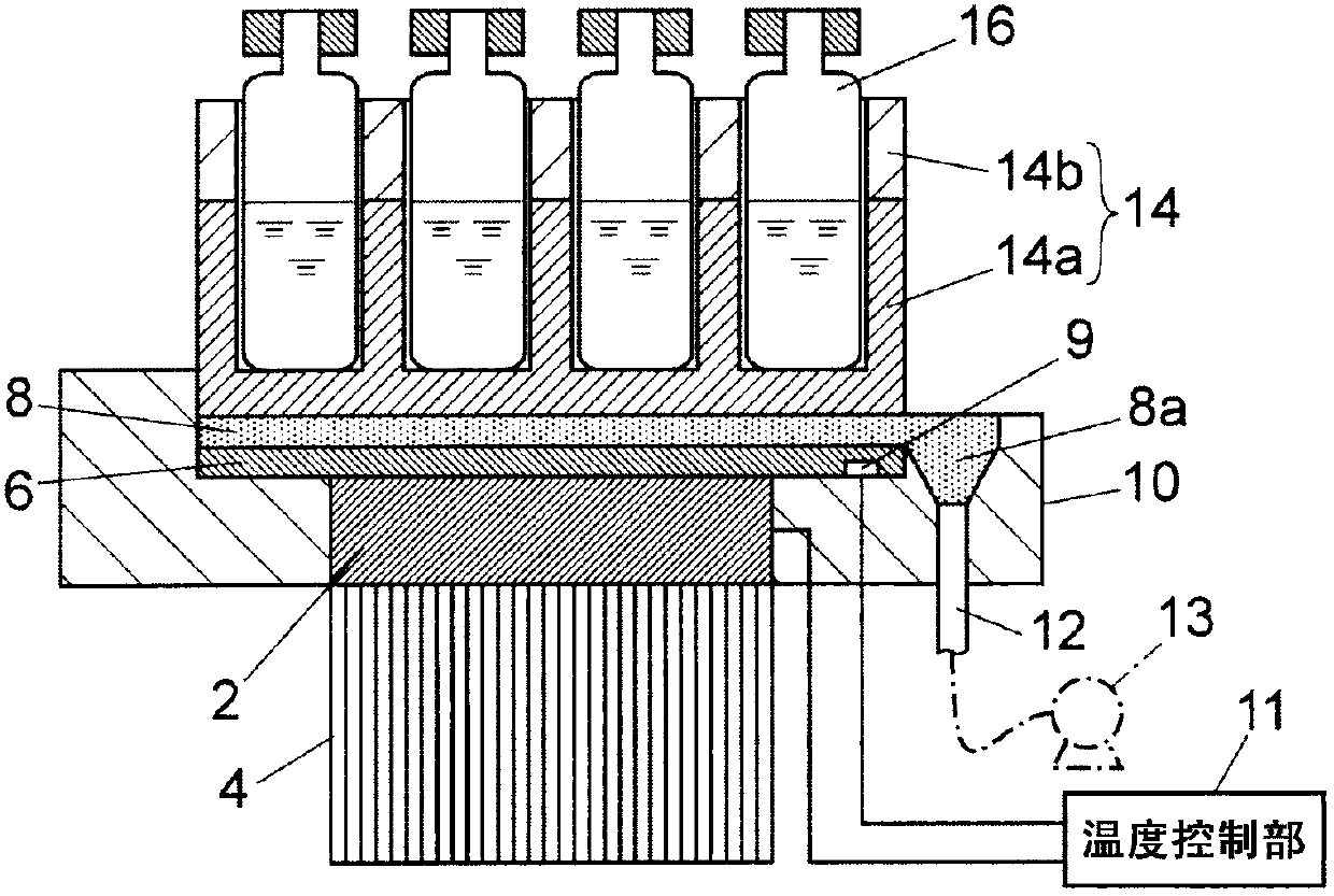
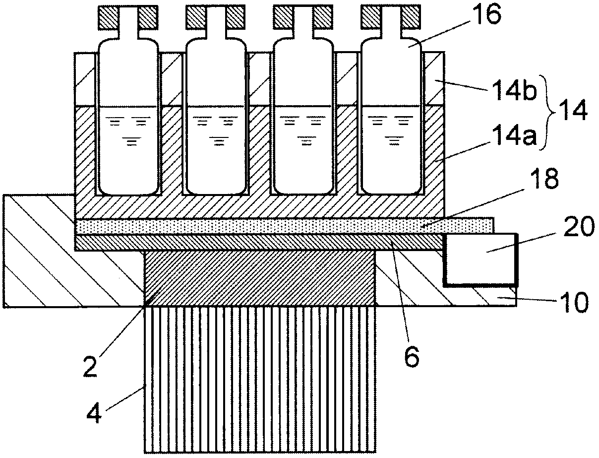
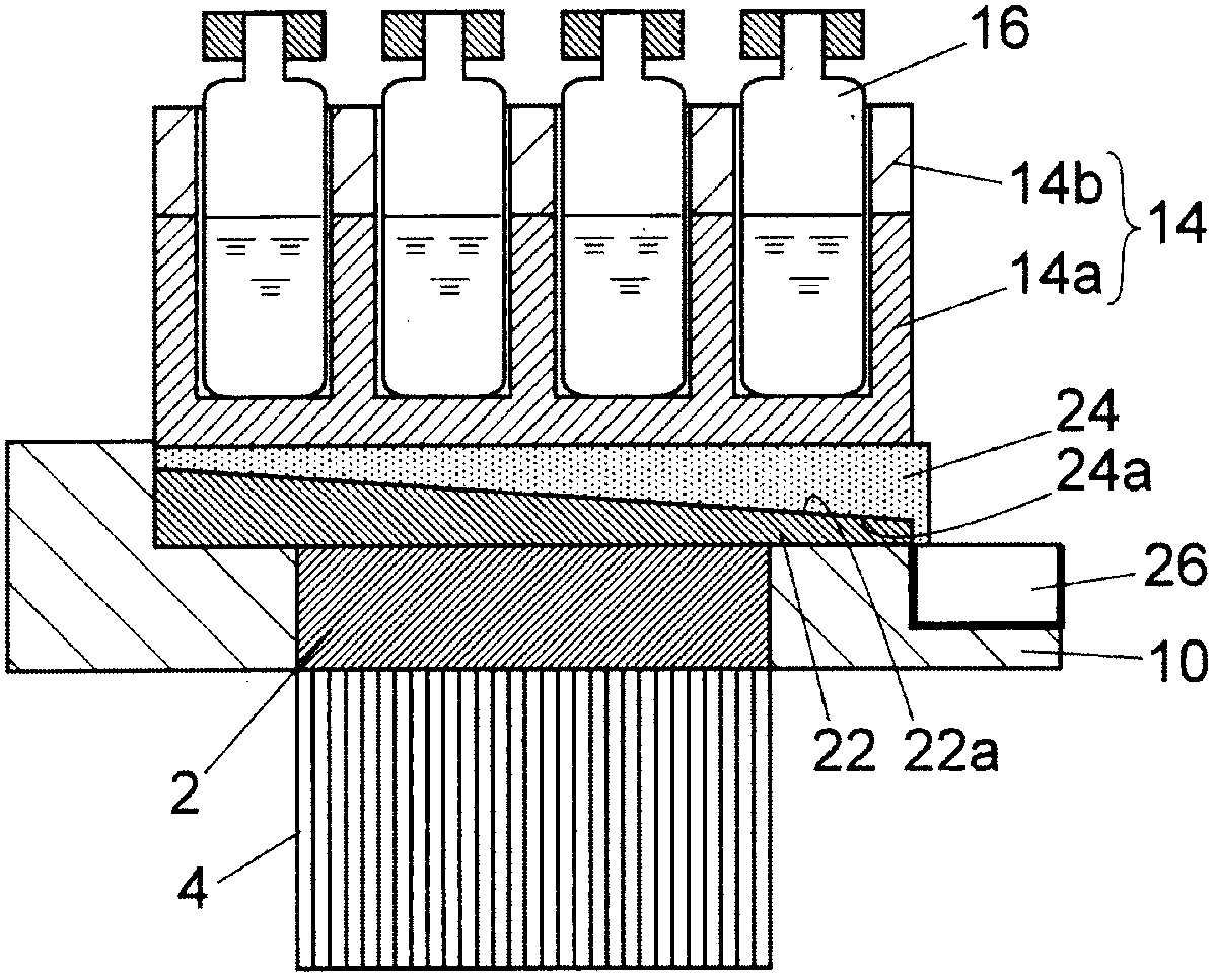
However, there is a problem that moisture in the atmosphere will condense on the surface of the sample container 16, the base 14a of the holder 14, and the surface of the heat transfer member 6 during the cooling process, resulting in dew condensation.

Method used


Image

  • Sample cooling device and sampling apparatus
  • Sample cooling device and sampling apparatus
  • Sample cooling device and sampling apparatus

Examples


Embodiment Construction

[0026] In a preferred embodiment of the sample cooling device of the present invention, a porous member having a plurality of holes having an inner diameter of a size to allow capillary force to act is used as the water absorbing member.

[0027] Examples of the porous member include an aluminum sinter, a stainless steel sinter, or a nickel sinter.

[0028] In addition, preferably, at least a part of the end of the water absorbing member is a drain extending from between the heat transfer member and the bracket to the outside for draining water absorbed by the water absorbing member from the water absorbing member. That is, the water-absorbing member extends to the outside of the facing region, and at least a part of the water-absorbing member existing outside the facing region serves as a drainage portion. In this way, the dew condensation water absorbed by the water absorbing member between the bracket and the heat transfer member is not discharged to the outside without ove...


PUM


Abstract

A sample cooling device for cooling a sample container held in a heat conductive rack comprises a cooler; a heat conductive member, on which the rack is placed, to be cooled in contact with the cooler; and a heat conductive water absorbing member disposed at least partly in an opposite region defined between the heat conductive member and the rack in contact with both of the heat conductive member and the rack. The water absorbing member has a structure for absorbing water by a capillary force.

Description

technical field [0001] The present invention relates to a sample cooling device for cooling a liquid sample before analysis in an analysis device for automatically analyzing a liquid sample such as a liquid chromatograph, and a sampling device provided with the sample cooling device . Background technique [0002] In an automatic analysis device that automatically injects and analyzes a plurality of samples into the device, there is a sample holder (hereinafter, simply referred to as a holder) for accommodating and setting a plurality of sample containers into which samples are added. ( See Japanese Patent Laid-Open No. 2011-99705.). [0003] For example, in the automatic analysis of a liquid chromatograph, if a rack containing a plurality of sample containers filled with a small amount of samples is set as a sampling device, the sampling device will collect samples from the rack according to a preset analysis program. The container sucks up the samples in sequence and inj...

Claims


Application Information

Patent Timeline
Patent Type & Authority Applications(China)
IPC IPC(8): G01N1/42G01N1/02G01N30/06
CPCB01L7/00B01L9/06B01L2300/1822B01L2300/1844B01L2300/1855B01L2300/1894B01L2400/0406F28F2013/006F28D15/00
Inventor 保永研一
Owner SHIMADZU SEISAKUSHO LTD
Learn More