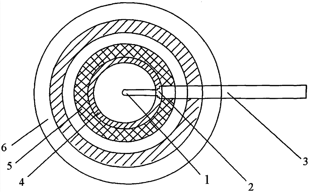
multilayer cavity ionization chamber

An ionization chamber and cavity technology, applied in circuits, discharge tubes, electrical components, etc., can solve problems such as uncertainty, achieve the effects of accurate measurement, cost savings, and avoid calibration steps

Active Publication Date: 2016-03-30
CHINA INSTITUTE OF ATOMIC ENERGY
View PDF6 Cites 0 Cited by
  • Summary
  • Abstract
  • Description
  • Claims
  • Application Information

AI Technical Summary

Problems solved by technology

However, this method has drawbacks. If a set of ionization chambers with different wall thicknesses is used, there will inevitably be uncertainty due to the difference in the sensitive volume, and the sensitive volume must be calibrated for each thickness of the ionization chamber.

Method used


Image

  • multilayer cavity ionization chamber
  • multilayer cavity ionization chamber
  • multilayer cavity ionization chamber

Examples


Embodiment 1

[0022] In this embodiment, the air kerma energy of high-energy photons with an average energy of 6.62 MeV is measured at a reference point of 1 m.

[0023] First, a basic thin-walled ionization chamber is selected, the thickness of the first layer of the chamber wall is 4mm, the material is graphite, and the sensitive volume of the basic unit is 50cm 3 . exist 137 The ionization chamber is calibrated in the Cs reference radiation field, and the ionization chamber is obtained at 137 Calibration factor N in Cs reference radiation field E , according to N E Make the change curve of the ionization current of the ionization chamber with the thickness of the chamber wall, that is, the effective weakening curve, and according to the following formula:

[0024] N D = 1 ρ · v · ( W e ...

Embodiment 2

[0033] The measurement object is the same as that in Embodiment 1, except that the connection mode of the hemispherical chamber wall is screw connection. The measured air kerma is 8.5μGy / h with a relative uncertainty of 3.3%.

[0034] The specific principle of measuring air kerma in the multilayer cavity ionization chamber provided by the present invention is:

[0035] The core formula for the measurement of high-energy photons is shown in Equation 1:

[0036] K a = ( μ tr μ en ) · K a , C . . . ( 1 )

[0037] It can be seen from formula 1 that the air kerma K is obtained by measuring the collision air kerma a,C , w...


PUM


Abstract

The invention belongs to the technical field of ionization radiation dose measurement, and discloses a multi-layer cavity ionization chamber. The ionization chamber consists of a basic thin-wall ionization chamber and a series of concentric chamber walls of different thicknesses, and is characterized in that proper concentric chamber walls are combined to obtain a ionization chamber with chamber walls of different thicknesses. The ionization chamber has the characteristics of easiness in operating and accurate measuring result.

Description

technical field [0001] The invention belongs to the technical field of ionizing radiation dose measurement, and in particular relates to a multilayer cavity ionization chamber. Background technique [0002] Ionization chamber measurement technology is one of the basic technologies of radiation dose measurement. Usually the ionization chamber is composed of a high-voltage electrode, a collector electrode and a shield electrode. Its structure can be flat, spherical, cylindrical, etc., and the inside is filled with an appropriate gas medium, usually air. By applying an appropriate working voltage, a uniform electric field is formed inside the ionization chamber to realize the charge collection of electrons and ions in the ionized medium, so as to achieve the purpose of radiation measurement. Taking the spherical ionization chamber as an example, the center of the sphere is the collector, and the spherical shell of appropriate material forms the high-voltage pole, which is also...

Claims


Application Information

Patent Timeline
Patent Type & Authority Patents(China)
IPC IPC(8): H01J47/02G01T1/02
Inventor 魏可新李景云侯金兵宋明哲王红玉高飞
Owner CHINA INSTITUTE OF ATOMIC ENERGY
Why Eureka
Try Eureka