Connector

A technology of connectors and receiving parts, applied in the direction of connection, components of connection devices, devices for preventing wrong connections, etc.

Active Publication Date: 2015-09-09
ORMON CORP
View PDF3 Cites 0 Cited by
  • Summary
  • Abstract
  • Description
  • Claims
  • Application Information

AI Technical Summary

Problems solved by technology

Therefore, the user has to determine whether the substrate is inserted into the proper position

Method used


Image

  • Connector
  • Connector
  • Connector

Examples


no. 1 example )

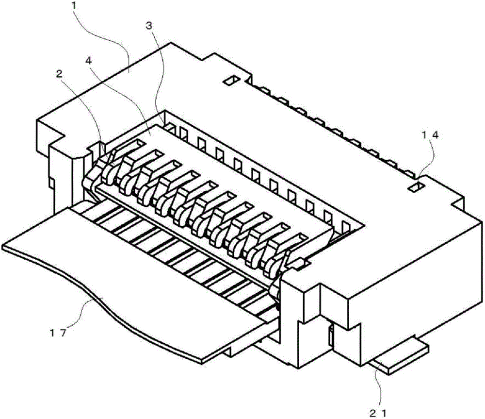
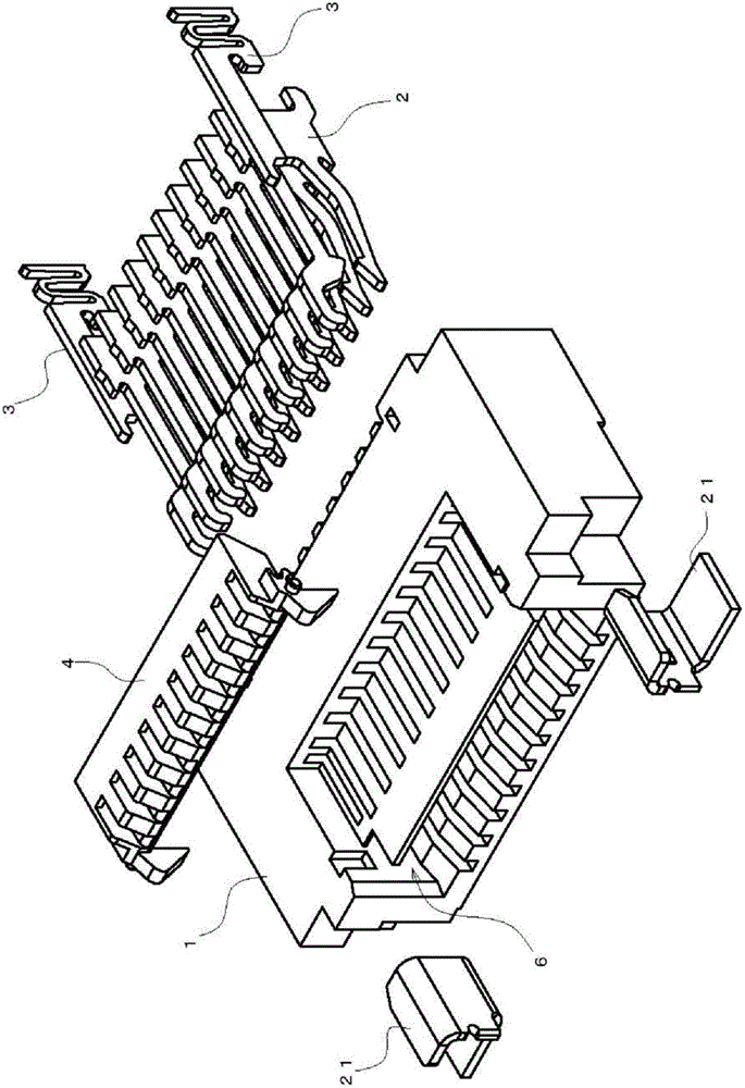
[0058] figure 1 is an overall view illustrating the connector according to the first embodiment, figure 2 is a perspective exploded view illustrating the connector. The connector is constituted by mounting the contact member 2 , the latch member 3 and the moving member 4 to the housing 1 .

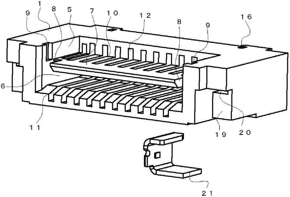
[0059] like Figure 3A and 3B As shown in , the case 1 is a product made by molding an electrically insulating resin material into a shape of parallel pipes approximately in a rectangular parallelepiped. A recess 5 and an insertion recess 6 are formed in the housing 1 . The recess 5 is open in the direction of the upper surface and the front surface. The insertion recess 6 is provided below the recess 5 and is open in the direction of the front surface. The recess 5 and the insertion recess 6 are separated by a partition wall 7 . Compared with the position of the front surface of the housing 1 , the front end portion of the partition wall 7 is located on the rear side, and the cuto...

no. 2 example )

[0079] Figure 13 A connector according to a second embodiment is illustrated. Since this connector differs from the connector of the first embodiment only in a part of the structure of the moving member 4, but is almost identical in other structures, the description of the structures without any difference will not be repeated.

[0080] like Figures 16A to 16B As shown, a plurality of guide walls 50 are formed at the rear end of the upper surface of the moving member 4 . The plurality of groove portions 49 arranged at predetermined intervals in the width direction constitute the plurality of guide walls 50 . A communication hole 51 communicating with the upper surface and the lower surface is provided at the front of the bottom surface of the groove portion 49 . The shaft portion 52 is formed between the guide walls 50 . The latch receiving portions 53 protrude forward from the guide walls 50 at both ends, respectively. A first lock recess 54 and a second lock recess 55...


PUM


Abstract

The present invention provides a connector in which insertion of a substrate up to a proper position enables achievement of an electrical connection between the substrate and a contact point member. The connector includes a housing with an insertion recessed portion into which a substrate is to be inserted, a contact point member that includes a contact point portion which is installed in the housing, protrudes into an insertion recessed portion, and is electrically connected to a conductive portion of the substrate to be inserted, and position determining member which moves the contact point member, when the substrate is inserted into the insertion recessed portion of the housing, in such a manner that the contact point member is retracted from the insertion recessed portion and then protrudes into the insertion recessed portion to make an electrical connection to a conductive portion of the substrate.

Description

technical field [0001] The invention relates to a connector. Background technique [0002] Conventionally, there is a well-known connector that prevents the lever from coming off even if there is a slight external force or vibration before or during the insertion of the flexible printed circuit board (substrate), thereby saving time and effort in the flexible printed circuit board insertion work. efforts (eg, Japanese Unexamined Patent Publication No. 2009-129860). [0003] However, regarding the conventional connector, only a structure has been disclosed which can prevent the lever from coming off due to vibration (for example, before insertion into the board or at other times). Therefore, the user has to determine whether the substrate is inserted into the proper position. Also, before or after making this decision, the user needs to operate the lever, that is, the user needs to raise or push down the lever. Contents of the invention [0004] The present invention is ...

Claims


Application Information

Patent Timeline
Patent Type & Authority Patents(China)
IPC IPC(8): H01R13/629H01R13/641H01R12/87H01R12/77
CPCH01R12/79H01R13/62H01R12/774H01R12/87
Inventor 的场正人岛田清司
Owner ORMON CORP
Why Eureka
Try Eureka