
Electrical power coupling with magnetic connections

一种联接件、联接部件的技术,应用在连接装置的零部件、连接、电气元件等方向

Inactive Publication Date: 2016-01-20
诺曼 R 伯恩
View PDF3 Cites 1 Cited by
  • Summary
  • Abstract
  • Description
  • Claims
  • Application Information

AI Technical Summary

Problems solved by technology

However, rigidly or semi-rigidly mounted connectors present some challenges, such as proper alignment of one connector with another

Method used


Image

  • Electrical power coupling with magnetic connections
  • Electrical power coupling with magnetic connections
  • Electrical power coupling with magnetic connections

Examples


Embodiment Construction

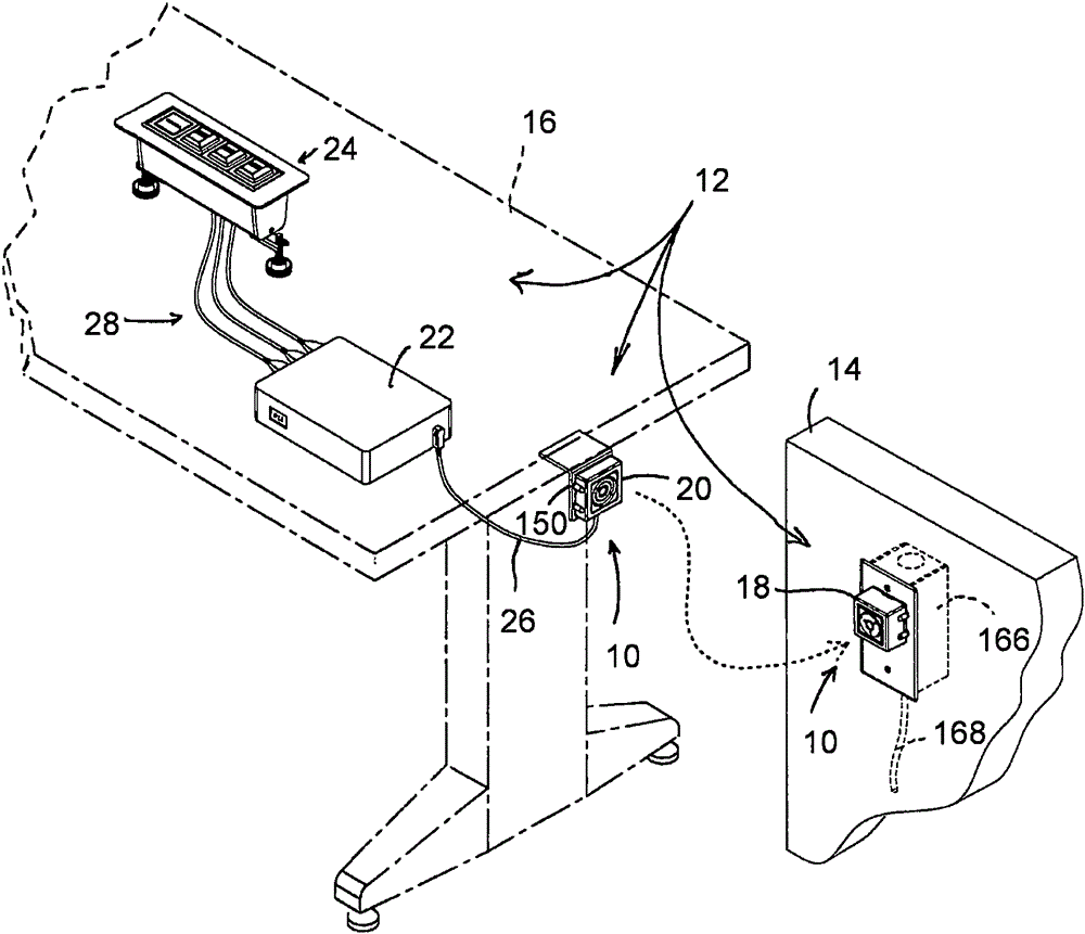
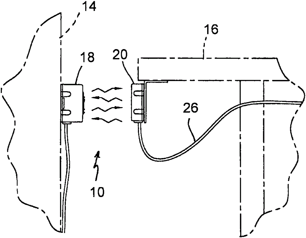
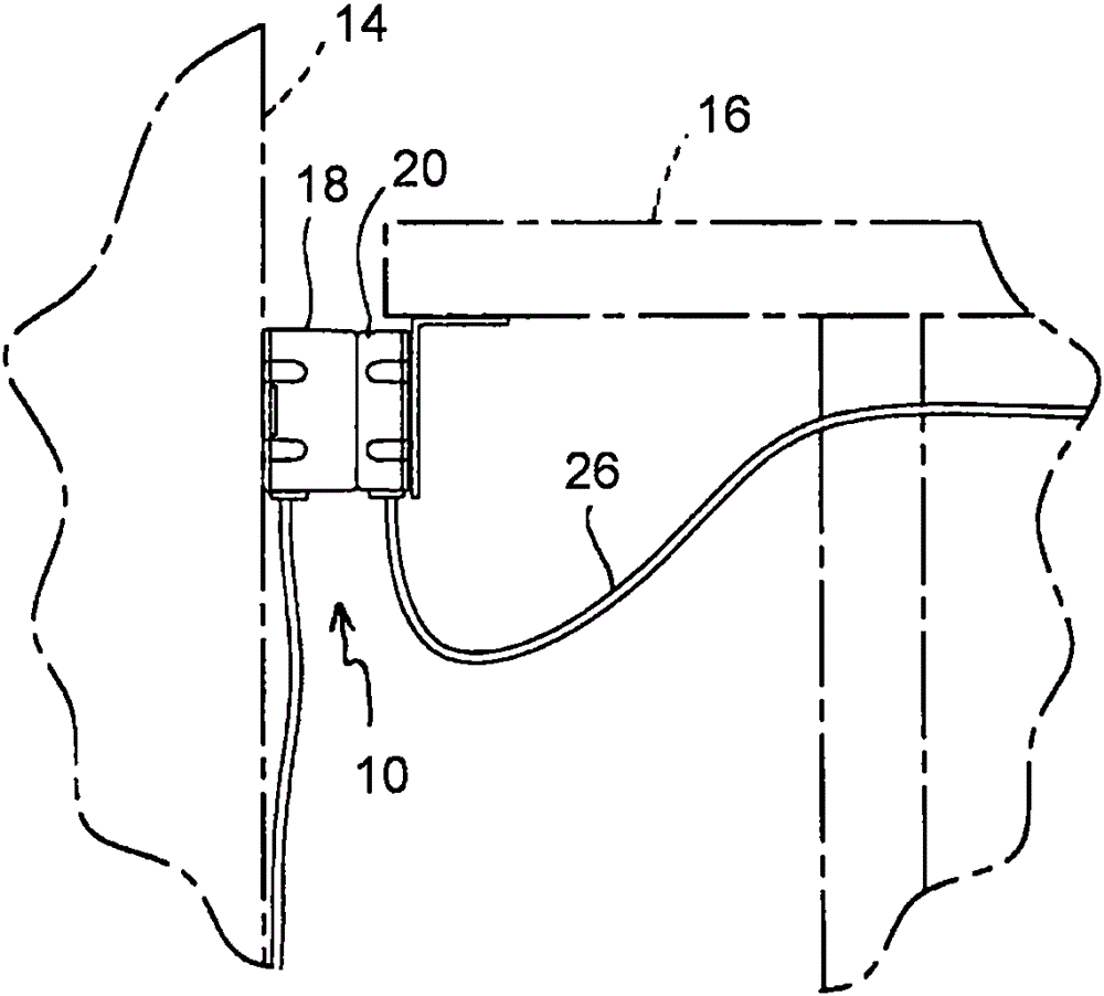
[0048] Referring now to the drawings and the illustrative embodiments described herein, a power coupling 10 is included in a power system 12 that can be installed along various surfaces (eg, wall surfaces 14 and furniture items 16), such as figure 1 shown. The power coupling 10 includes a power transmitter 18 and a power receiver 20 each having respective power coupling components arranged such that the power coupling components are configured to engage with each other and thereby provide a connection between power transmission A direct electrical connection can be established between the power transmitter 18 and the power receiver 20 even when the power transmitter 18 and the power receiver 20 are not aligned with each other and / or are at different rotational positions relative to each other.

[0049] exist figure 1 In the illustrated embodiment, the power system 12 further includes a power storage unit (eg, a battery) 22 and an electrical receptacle unit 24, both mounted to...


PUM


Abstract

An electrical power coupling includes a pair of power coupling parts, each having a base and a coupling portion that is movable relative to said base. Each coupling portion has first and second electrical contacts that are spaced laterally outboard, by respective first and second distances, from centers of the coupling portions. Magnetic elements attract the respective coupling portions to one another when the coupling portions are positioned closely to one another. Each coupling portion moves relative to its respective base to align the coupling portions with one another and establish electrical connections between the first electrical contacts and between the second electrical contacts. Optionally, at least two electrical contacts are arcuate or circular in shape.

Description

[0001] Cross References to Related Applications [0002] This application claims priority to US Provisional Application Serial No. 62 / 022,740, filed July 10, 2014, the entire contents of which are hereby incorporated by reference. technical field [0003] The present application relates to a power supply and / or electronic data output device, socket and connector for establishing a direct electrical connection between individual electrical conductors. Background technique [0004] Many different types of power and electronic data connectors have been designed for transferring power or electrical signals from one or more electrical conductors to another electrical conductor or conductors. For example, male-female electrical connectors are often used to establish proper connections for compatible conductors, whether for power or data signal transmission. While connectors are often provided at the ends of individual flexible cables, in some applications, such as in workspace en...

Claims


Application Information

Patent Timeline
Patent Type & Authority Applications(China)
IPC IPC(8): H01R13/62H01R13/631H01R24/00
CPCH01R13/6205H01R13/2421H01R25/162
Inventor 诺曼·R·伯恩R·D·布蒂M·A·米切尔N·J·莫罗
Owner 诺曼 R 伯恩
Learn More