Dual-rotor flux-switching permanent-magnet motor

A magnetic flux switching, permanent magnet motor technology, applied in electrical components, electromechanical devices, magnetic circuit rotating parts, etc., can solve the problems of low utilization rate of permanent magnets, magnetic flux leakage, etc. Volume quality, the effect of reducing dosage

Inactive Publication Date: 2013-09-18
NANJING UNIV OF AERONAUTICS & ASTRONAUTICS
View PDF7 Cites 13 Cited by
  • Summary
  • Abstract
  • Description
  • Claims
  • Application Information

AI Technical Summary

Problems solved by technology

[0004] In order to solve the problems of serious flux leakage and low utilization rate of permanent magnets in the existing magnetic flux switching permanent magnet motor, the present invention proposes a double rotor flux switching permanent magnet motor

Method used


Image

  • Dual-rotor flux-switching permanent-magnet motor
  • Dual-rotor flux-switching permanent-magnet motor
  • Dual-rotor flux-switching permanent-magnet motor

Examples


Embodiment 1

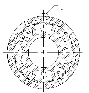
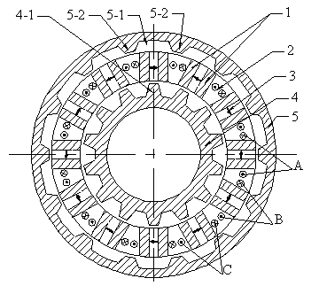
[0029] Example 1: Combining figure 2 with image 3 The dual-rotor flux switching permanent magnet motor of the present invention includes a stator and two rotors, and the speed and direction of rotation of the inner rotor 4 and the outer rotor 5 are the same.

[0030] The stator is composed of several stator modules, which form a circle. Each stator module consists of two stator core teeth 1-1, 1-2, an armature winding 2 and a permanent magnet 3. The permanent magnet 3 is located between two magnetically permeable stator core teeth 1-1 and 1-2, forming a sandwich module structure of two iron cores and permanent magnets. Two permanent magnets in adjacent sandwich structures have opposite magnetization directions. There is a through slot 6 between the two stator modules, and the armature winding 2 is inside the through slot 6 . The armature winding adopts the concentrated winding structure according to the phase sequence of A-B-C, and is wound on the interlayer module compo...

Embodiment 2

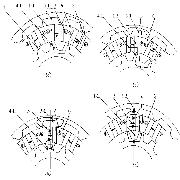
[0037] Embodiment two: see Figure 4To illustrate this embodiment, the difference between this embodiment and the dual-rotor flux switching permanent magnet motor of Embodiment 1 is that on the stator, since the stator is a sandwich module structure composed of discrete stator core teeth and permanent magnets, and the winding in the through slot The composition of the winding is not convenient for the winding of the winding, and the stator module needs to be installed and fixed by an external supporting structure. Therefore, a non-magnetically permeable beam 9 connecting the two stator modules is installed in the slot. The beam is made of non-magnetic or weakly permeable metal material with good strength, and is welded together with the stator core teeth. The through slot is divided into upper and lower layers, each layer contains a positive winding of one phase winding and a negative winding of another phase winding, and the same phase windings of the upper and lower layers c...


PUM


Abstract

The invention provides a dual-rotor flux-switching permanent-magnet motor and belongs to the technical field of electric motors. The dual-rotor flux-switching permanent-magnet motor comprises a stator, an inner rotor and an outer rotor, wherein the stator is formed by connecting a plurality of stator modules, each stator module is composed of a stator iron core tooth (1), a permanent magnet (2) and an armature winding (3), the inner rotor (4) and the outer rotor (5) are located on the inner circle and the outer circle of the stator respectively, and independent air gaps are formed between the inner and outer rotors and the stator respectively. With the change of relative positions of the stator and the rotors, paths of flux emitted by the permanent magnets are switched continuously, and when the flux of a winding linkage is maximum, the paths of the flux are emitted by the permanent magnets and closed by the inner and outer air gaps, the inner and outer rotors and the stator iron core teeth. According to the motor, the defects that traditional flux-switching permanent-magnet motors are serious in flux leakage of outer circles of stators and low in utilization ratio of permanent magnets are overcome, and the torque and the power density of the motor can be improved.

Description

[0001] technical field [0002] The invention belongs to the field of motors, in particular to a dual-rotor magnetic flux switching permanent magnet motor. Background technique [0003] The permanent magnets and armature windings of the flux switching permanent magnet motor are located on the stator, which is easy to achieve simultaneous cooling of the windings and permanent magnets. There is neither permanent magnet nor winding on the rotor. The rotor structure is simple, durable, and suitable for high-speed operation. Moreover, the flux linkage of each phase winding chain changes in bipolarity, and the back emf constant of the motor is higher than that of unipolar poles. Therefore, the torque density and power density of the flux switching permanent magnet motor are high. It is used in wind power generation and electric vehicles. and other fields have broad application prospects. However, existing magnetic flux switching permanent magnet motors have serious flux leakage f...

Claims


Application Information

Patent Timeline
Patent Type & Authority Applications(China)
IPC IPC(8): H02K16/02H02K1/24
Inventor 黄旭珍周波陈琦魏佳丹
Owner NANJING UNIV OF AERONAUTICS & ASTRONAUTICS
Why Eureka
Try Eureka