Isolated flyback converter with sleep mode for light load operation

A sleep mode and converter technology, applied in the direction of output power conversion devices, high-efficiency power electronic conversion, instruments, etc., can solve problems such as VOUT rise

Active Publication Date: 2013-09-18
ANALOG DEVICES INT UNLTD
View PDF13 Cites 42 Cited by
  • Summary
  • Abstract
  • Description
  • Claims
  • Application Information

AI Technical Summary

Problems solved by technology

However, when the actual load current drops below the threshold current, the required minimum duty cycle of the converter 10 produces too much current and causes VOUT to rise above the regulated voltage

Method used


Image

  • Isolated flyback converter with sleep mode for light load operation
  • Isolated flyback converter with sleep mode for light load operation
  • Isolated flyback converter with sleep mode for light load operation

Examples


Embodiment Construction

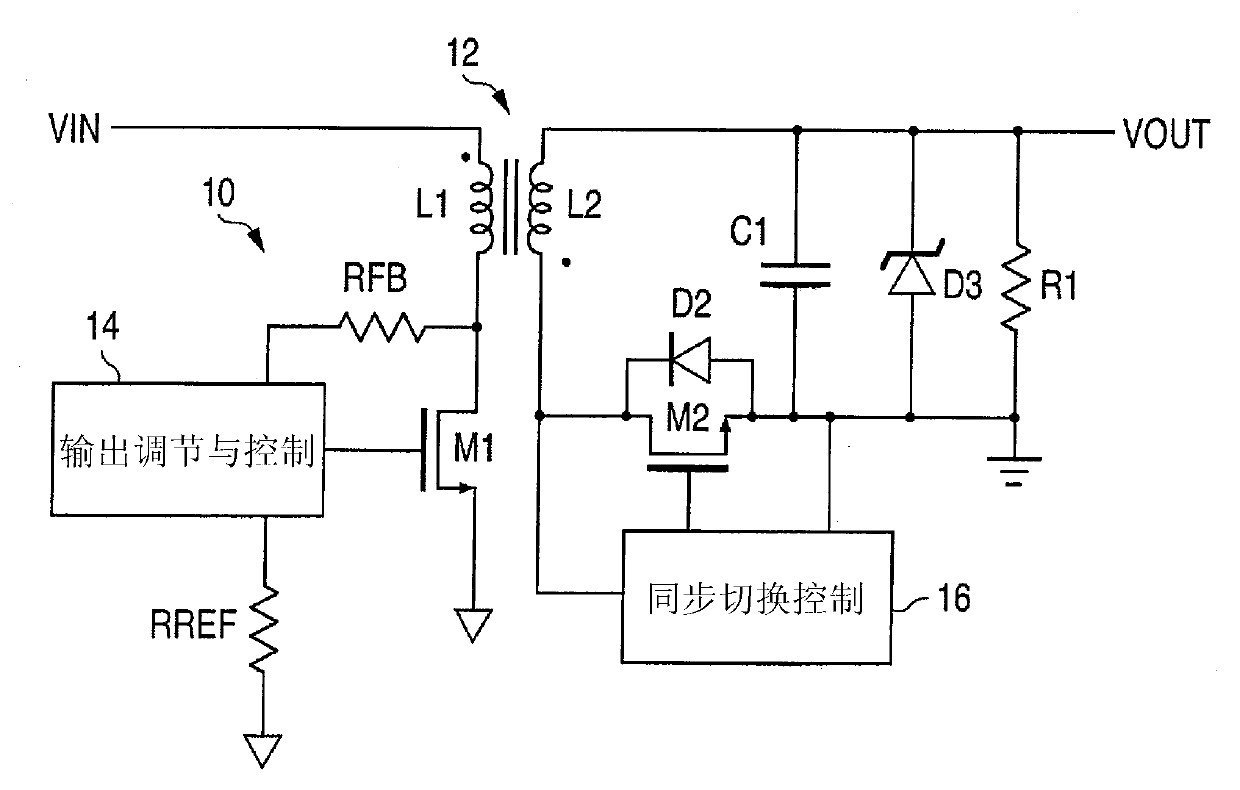
[0040] image 3 represents any of many types of flyback converters that use primary-side sensing of the output voltage VOUT. Since the present invention is only concerned with the operation of the converter when overvoltage occurs during low load current conditions, any conventional aspect of a flyback converter can be used for medium to high load currents. Since this conventional circuit is well known and there are many types (eg, current mode, voltage mode, variable frequency, fixed frequency, etc.), a detailed description of this conventional circuit is not required. The description of the conventional aspects of the converter 10 of Figure 1 applies to image 3 The converter 20.

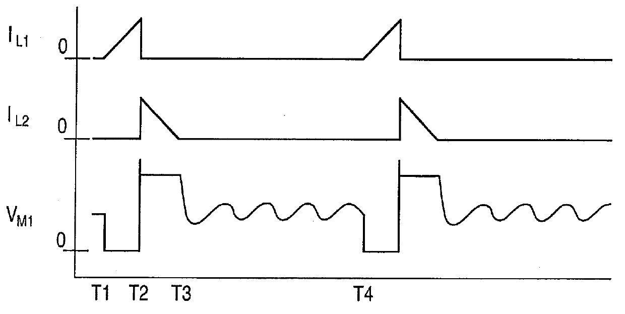
[0041] For medium to high load current operation, converter 20 periodically turns on MOSFET M1 to charge primary winding L1. The duty cycle or peak current of MOSFET M1 depends on the feedback voltage at the drain of MOSFET M1 related to VOUT, which is sampled at a specific time when synchronous ...


PUM


Abstract

In a flyback converter using primary side sensing to sense the output voltage for regulation feedback a comparator on the primary side detects whether the output voltage has exceeded a predetermined regulated voltage by a first threshold to detect an over-voltage condition, resulting from a current generated by the converter exceeding the load current. Triggering of the comparator causes the converter to enter a non-switching sleep mode, whereby the output voltage droops over a period of time. When the output voltage has dropped below the predetermined regulated voltage by a second threshold, a synchronous rectifier is controlled to turn on, then off, to generate a pulse in the primary winding. Upon detection of the pulse, the sleep mode is terminated, and normal operation resumes until a regulated voltage is achieved or until the first threshold is again exceeded by the output voltage.

Description

technical field [0001] The present invention relates to DC-DC flyback converters using synchronous rectifiers, and in particular to such flyback converters using primary side sensing to detect the output voltage. Background technique [0002] DC-DC flyback converters using synchronous rectifiers are well known. When isolation between the input and output stages is required, the output voltage can be sensed by various methods for regulation feedback. Some ways to deliver the output voltage while maintaining isolation include using an optocoupler or using an auxiliary winding on the primary side of the transformer. However, those approaches require additional circuitry, space, power and cost. [0003] A more elegant way of detecting the output voltage is to sense the voltage at the terminals of the power switch when it is turned off during the discharge (or flyback) cycle of the converter. The voltage at the terminals of the power switch is due to the current in the seconda...

Claims


Application Information

Patent Timeline
Patent Type & Authority Applications(China)
IPC IPC(8): H02M3/335H02M1/00
CPCH02M3/335Y02B70/10H02M1/0032
Inventor 约翰·D·莫里斯迈克尔·G·内格雷特陈敏
Owner ANALOG DEVICES INT UNLTD
Why Eureka
Try Eureka